Home › Forum › Ask A Member › 1940 Johnson HD-15 Magneto testing
- This topic has 37 replies, 3 voices, and was last updated 6 years, 9 months ago by
 Buccaneer.
-
AuthorPosts
-
June 24, 2017 at 10:24 pm #7421
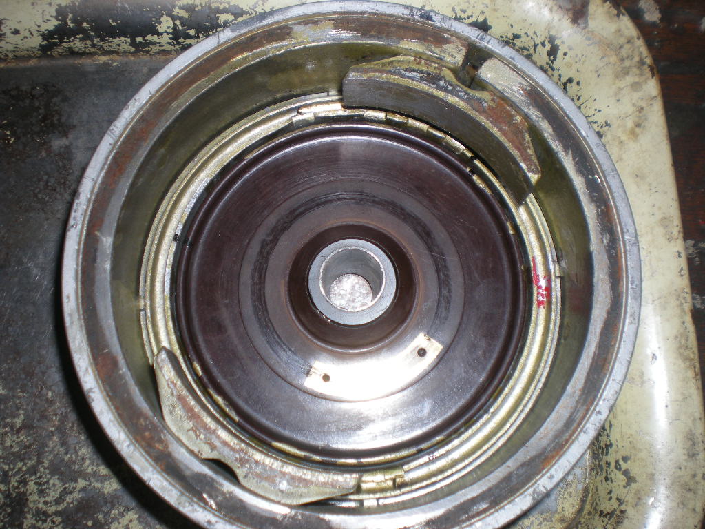
Now that I have a Steven’s ST-75 tester, I decided to pull
the magneto back off the troublesome "subject" Johnson.
This is the video I took a while back of it running
very erratic.
https://youtu.be/aPybyPCCht8I believe I got the twin cylinder "one coil" system
hooked up to the tester correct, as it made spark!
I grounded one plug wire to the mag plate, and hooked
up my "secondary" lead to the other.
Primary tester leads hooked up normally.
I tested twice, grounding the different plug
wires to the mag plate, and both times it
made steady spark at around 2.6 amps.
===========================================
Update- I just found the "specs" for this coil and
it say 2.5 amps, Reverse Polarity. I had
it hooked up normal polarity, so perhaps
it would have sparked at a lower amperage
if I hooked it up correctly. 🙁
I can retest tomorrow, but not sure what that will
prove as I didn’t find any arcing / leakage before.
=======================================
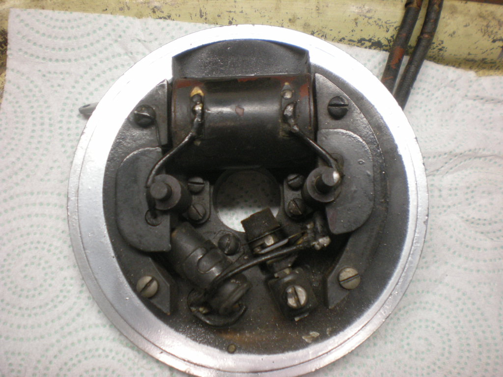
I then used the leakage "probe" and didn’t find
any obvious leaks, but if you got the probe anywhere
near the top near the top of the ground brush towers,
she’d arc nicely from the brushes!
I did get some "tiny, tiny" arcs from around
the tower mounting screws, but this appeared to be
some kind of inductance spark like I noticed on
a different coil.
I see no carbon tracking on the flywheel bakelite grounding
plate, and I have cleaned it twice before with electrical contact cleaner.
The coil checks out on the Ohm meter at .1K primary, and 6.38K secondary.I guess I’m kinda at a loss of what to do next.
From the video, does it sound like an electrical problem?
Thanks for your thoughts!
Attachments:
Prepare to be boarded!
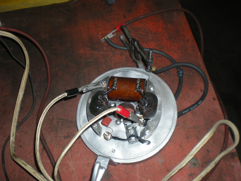
June 25, 2017 at 1:01 am #60267You might want to insulate your capacitor wire with some shrink rap where it hooks up to positive side of coil. Also what type of capacitor and value are you using? Should be like a .09 – .125 shouldn’t it?? that’s way lower than the .2 or .22
Joe
June 25, 2017 at 2:51 am #60271Joe, it’s been a while, so I have no recollection on how
I chose to use that .2 uf capacitor. I may have checked
the capacitance of the original, been steered to using
it, or just plain didn’t think about it!
Not sure if I have the original in the photo to check,
but will look tomorrow.
I see the parts list calls for a 71-1555 condenser.
I doubt if that 1940 parts number is going to help!
Would a "wrong" capacitance cap cause a motor
to run that irratic?
Should I be putting shrink wrap on all those orange
caps I use?
Thanks for the ideas!
Attachments:
Prepare to be boarded!
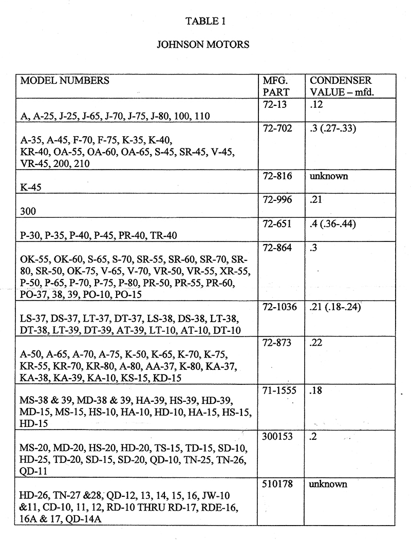
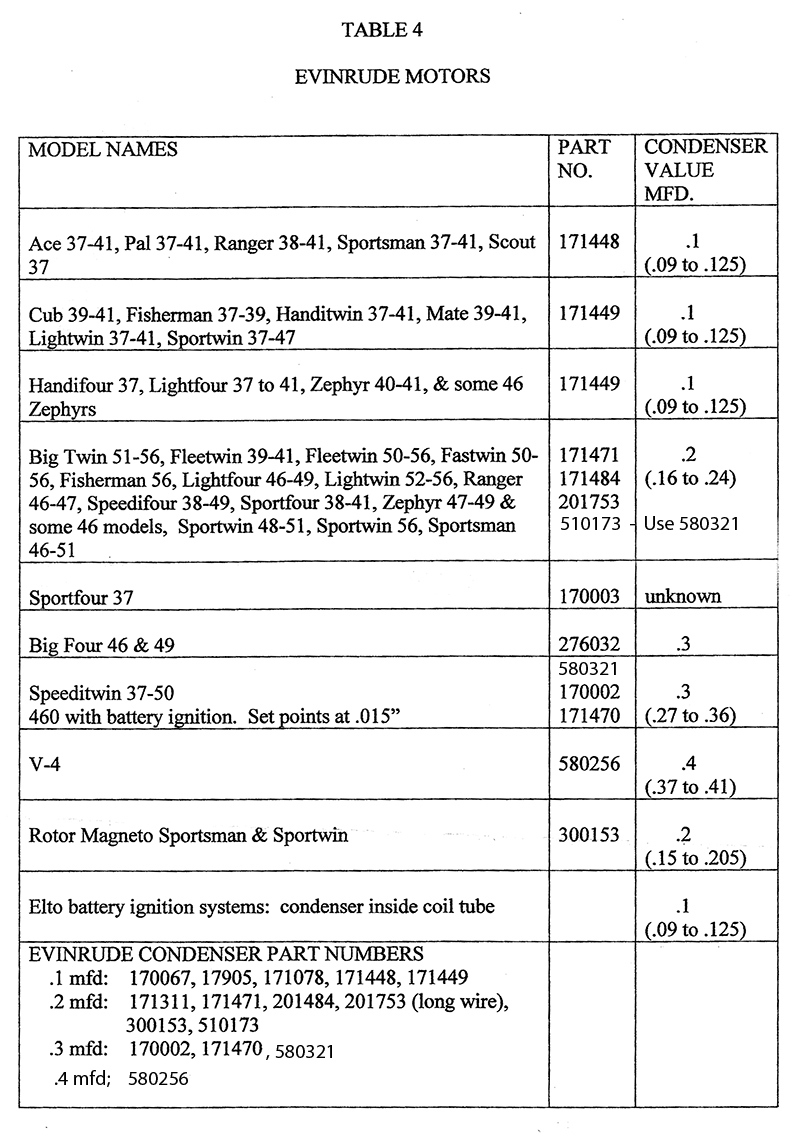
June 25, 2017 at 3:03 am #60273I think this is how I came by using a .2uf cap
for the HD-15. This table says .18
Attachments:
Prepare to be boarded!
June 25, 2017 at 3:12 am #60274I just put shrink rap on the leg of capacitor that goes to the points. When that baby is running producing max voltage who knows might be making it miss? They insulate the condenser wire.
I know most the time the condenser value is married to the coil used. I can’t say that’s your problem but what if it is. I was looking at the condenser chart for a 1940 – 1941 Zephyr it runs a similar coil and it was showing .09-.125
I hope that helps,
Joe
Attachments:
 June 25, 2017 at 3:16 am #60275
Found a member’s video of a HS-15 Johnson running.
Here’s what they’re suppose to sound like, lol
https://youtu.be/EkwokfkpGs0Prepare to be boarded!
June 25, 2017 at 11:31 am #60282Found this other thread here on our forums.
viewtopic.php?t=10117
"Can someone explain the theory in detail on how this point setup works with the carbon brushes? Found a .18 mfd condenser but still can’t get it to fire."
Then Response
"I’ll be daring and give it a try. You have an alternate firing two cylinder with the coil from an opposed twin. Testing the coil is done like an opposed twin where you test across the plug leads if you have the flywheel off – not lead to ground like a normal alternate firing twin. When everything is working the brushes ground alternate sides of the coil. To do that on the underside of the flywheel is a bakelite disk for an insulator. There are grounding points in it. The brushes make contact on each side and provide the alternating spark. The brush holders have to be clean and provide insulation for the brushes and there has to be contact through the grounding points with the flywheel. Once everything is clean and correct magic happens.
Did that help any? Experts don’t be afraid to jump in here."Here are my thoughts below:
Watching your video when you tried to ground each plug it was like no real definite reaction like a cylinder that isn’t firing seem like both weren’t firing evenly their firing sporadically or one is double firing.
Have you checked the flywheel bakelite for cracks. Possibly rig/attach like an omc high tension side coil wire to flywheel using your stevens meter and check it all around bakelite for arching with your probe?? Also check the metal ground point on flywheel for arching I am guessing it should arch in that spot??
Thinking to myself what I would do. What if you use a timing light on engine. With magneto in a fixed position where motor will run. Make marks on flywheel and engine for both cylinders where points open so with the light you could see if while its running if your getting double fire on a cylinder instead of single fire?? You could make the marks different colors or a big number 1 and big number 2. If a cylinder is double firing that’s a brush problem but it might help you identify which brush. Also if its double firing the brass tab in flywheel might not be grounded correctly the stevens meter probe test should tell if it is or not.
Joe
June 25, 2017 at 12:38 pm #60283Joe, thanks again for your thoughts.
I seen that other thread and glad to
see I’m not the only one ever having
troubles with this type of mag!When I was grounding out the spark plugs
(in the video) I didn’t get the reaction one
normally would, but if I remember correctly,
the reaction seemed "more normal" when
shorting out one cylinder than the other.I’m not sure "how" or "if" the Stevens ST-75
could be used to Hi-Pot the bakelite
plate in the flywheel. I’d really be bummed out
if I fried my new found Stevens 😮
Anyone have thoughts on if it’s "doable?"Joe, regarding the timing light, that’s an interesting idea.
Being that there’s only one set of points, I would think
theoretically, the timing between cylinders would
be automatically synced?
I guess I could use my "buzz box" on the points (if I can snake
a wire up through the bottom of the mag plate) and mark
a spot on the flywheel for the top cylinder where the
buzz box sounds off (points open), then do the same
for the bottom cylinder, as you say, using different color
markers.
If the plugs are indeed firing between "top dead center" of
the piston strokes, the timing light should be flashing
in places other than "on" the colored marks, and I might
break out in a disco dance?
Is this the general idea?
I think my old Sears timing light still works….. guess it’s
worth a try if I can get the HD-15 started again!
Thanks for the ideas!Prepare to be boarded!
June 25, 2017 at 12:44 pm #60285With rigging up the flywheel take a omc coil and a piece of plug wire put one side of plug wire into omc coil like normal on the other side ground it to your flywheel. Note: flywheel is off engine sitting on work bench. Then hook up omc coil like normal to stevens tester and use the probe to go around checking bakelite and brass tab for arching. Bakelite shouldn’t arch tab should ark. Does that make sense or am I off base on that.
I am guessing you got 2 lobes on the cam that opens points. Thats how I would make my marks when the points open for each respective cylinder. You are right in what I am thinking timing isn’t the issue but double firing might be happening that is what I think my test might determine
Joe
June 25, 2017 at 1:19 pm #60290Joe, I think I understand your "hook-up" for testing
the flywheel bakelite with the Steven’s probe.
I drew it out on a piece of paper and think it could
work. Maybe I’ll upload a drawing of said plan
later.
I’ll have to look at the cam, I can’t recall if it has
to lobes or not.
Gotta go walk the dog between rain showers!
Thanks!Prepare to be boarded!
-
AuthorPosts
- You must be logged in to reply to this topic.