Home › Forum › Ask A Member › Success…Lauson Pony Coil Converison w/ video
- This topic has 17 replies, 8 voices, and was last updated 10 years, 5 months ago by
ddoyle.
-
AuthorPosts
-
May 25, 2015 at 11:19 pm #16872
Mas, let me look, Im sure I have something that would help you out.
May 26, 2015 at 1:45 am #16895This is what I have –

. . . . . 😉

 May 26, 2015 at 1:48 am #16896
Thank you guys for the insight. My only question is what determines the required capacitance? Is it the coil, flywheel magnet strength, point gap, plug type, plug gap, RPMs, material used…or all of the above??
Thank you for your help!
Mas
May 26, 2015 at 2:30 am #16898Mainly the coil, the magnets have a lesser influence.
May 26, 2015 at 2:30 am #16899@Chris_P
That’s really interesting info..
Back in the old days, 1920s-1930s, the cost of high-voltage & value condensers was much greater than today. If they used higher values, it would seem that it was a genuine necessity.. rather than just allowing a bit of slop.
If they used lower values, then that would make more sense.. as it’s down to what they can get away with, for the money. I’ll be saving your post for later reference.
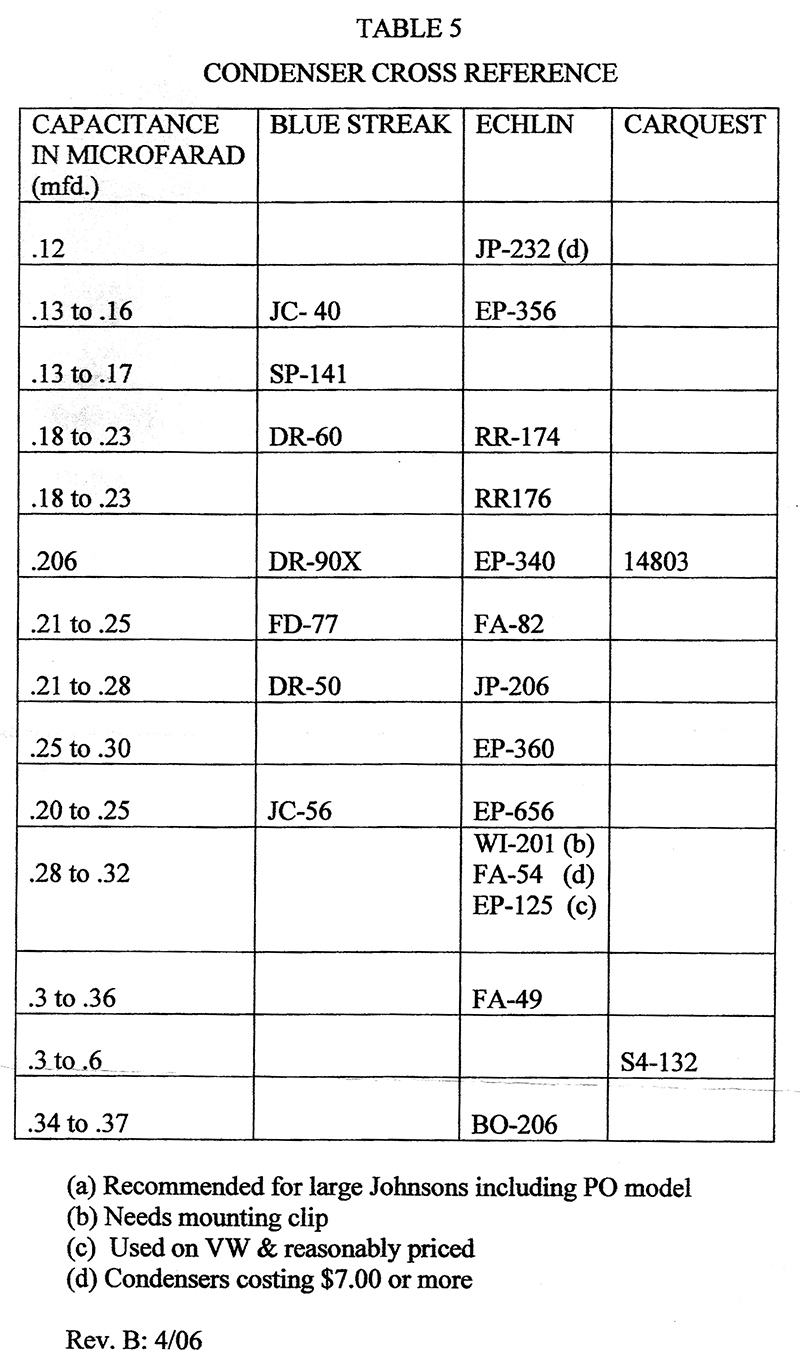
ETA: @Gary – that’s brilliant! I’ve never seen such a chart.. thanks so much for posting it.
May 26, 2015 at 2:35 am #16901quote Mas:Thank you guys for the insight. My only question is what determines the required capacitance? Is it the coil (…)As I understand it, it’s primarily the inductance of the coil’s primary winding. The condenser forms a "tank circuit", which is a (frequency) tuned circuit, with the primary inductance. This means that the condenser / primary winding are most efficient at a particular frequency – and if you’re thinking, you already realize that the frequency is directly related to the speed of the engine.
In short, a given combination of condenser value and coil inductance is most efficient at a particular frequency – aka a given RPM range.
ETA: Gary had it.. it’s almost entirely the inductance of the coil’s primary winding.
May 27, 2015 at 10:50 am #17011quote Chris_P:I would say for the 40s/50s/60s vintage magnetos, a lot are in the .18 to .22 range. Cannot really go wrong with .20 uf.As the motors vintage gets earlier, the uf rating vary.
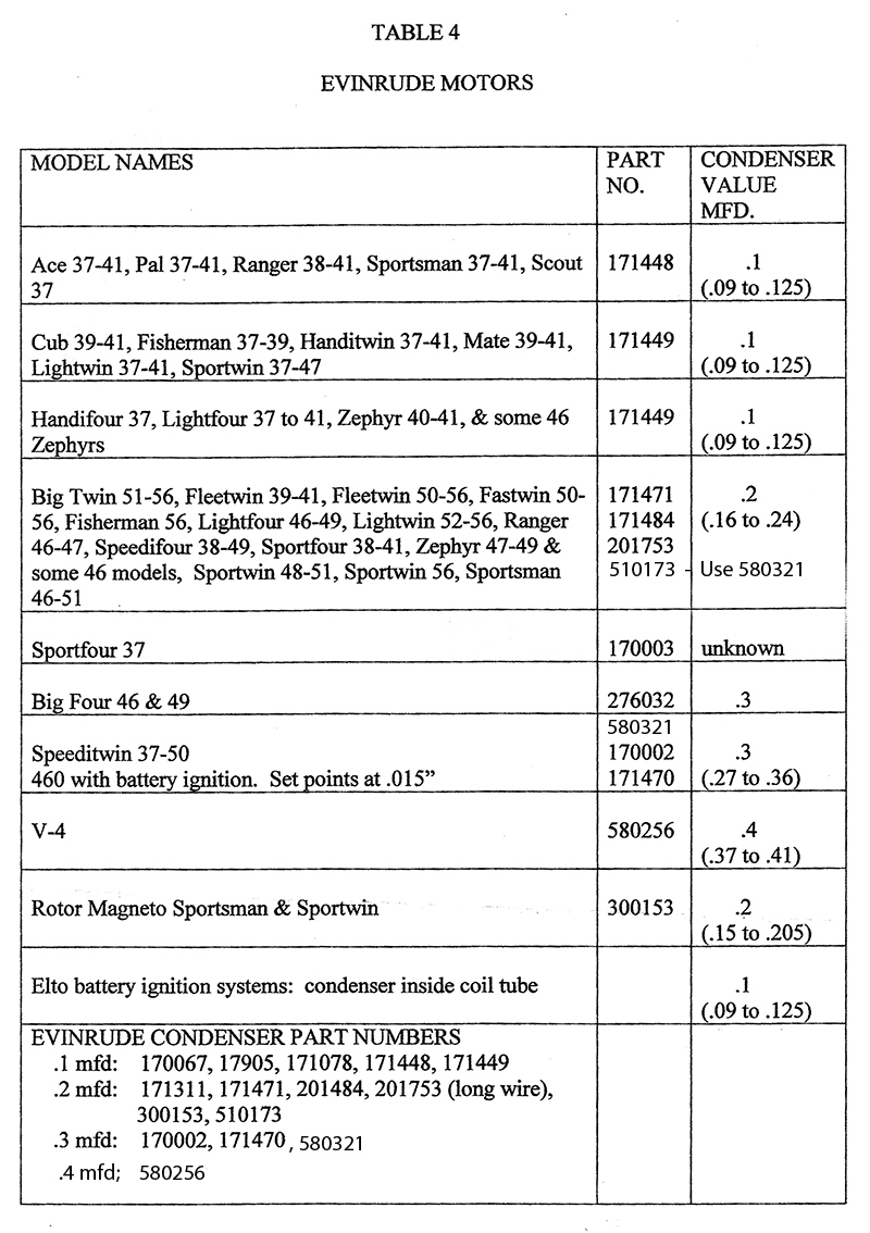
30s vintage motors average more in the .4 uf range (.36 to .44) These include the P30,P35, P40, P45, PR40, TR40, etc…. and Evinrude counterparts
Motors slightly older than that, such as the A35, A45, VR45, and the like had roughly a .3 uf rating (.27 to .33), and Evinrude counterparts Big Four, Speedi Twin, 460.
Very early motors, such as the A, A25, J25 had a much lower uf rating, as low as .09, but most I have tested are around .12, Evinrude counterparts Ace, Pal, Ranger, Cub, etc…
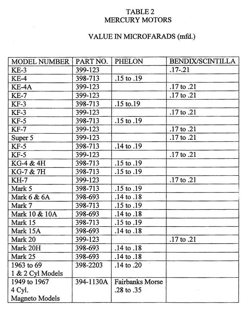
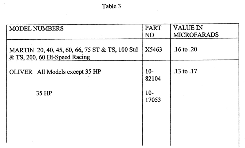
Mercs and Martins are all around .16 to .21
Olivers slightly lower at .13 to .17
Call me a weirdo, but I have a pretty good collection of condensors. Don’t ask me why. Also like to collect Magneto testing equipment, and manuals.
My wife wants to lock me up.
where do you find your condensers for the the Cub,Pal etc..Chris? 😕
May 27, 2015 at 4:25 pm #17030Anyone who does not print those tables is Crazy! Huge thanks
-
AuthorPosts
- You must be logged in to reply to this topic.