Home › Forum › Ask A Member › OMC Kill-switch question
- This topic has 25 replies, 5 voices, and was last updated 1 year, 6 months ago by
fleetwin.
-
AuthorPosts
-
June 27, 2024 at 11:06 am #288667
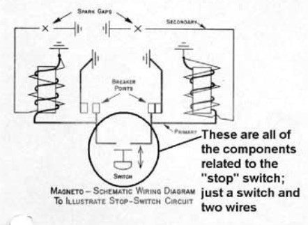
As I’m sure you all know, the OMC 2-cyllinder kill switch is a pretty idiot-proof circuit: connect the coil-side of the points together, and the engine dies. Simple concept, really…since, at any given moment of revolution, one of the points is closed-to-ground, by tying them together both points are now grounded, killing spark.
Here’s the schematic from OMC’s service letter showing the circuit.
My engine has the 2 wires run to a [dedicated, maintained] toggle switch on the dash of my boat, and it works as designed….sort of. At low to medium RPM, it kills the engine. But at high RPMs, is doesn’t. Yes, the engine’s performance goes to crap as it tries to die, but it’s as if the points manage to “ride through” somehow, allowing just enough gap to keep it running (albeit very poorly).
I have tested & tested & tested again: with 2 fluke meters attached, and a manual turn of the flywheel, I can assure you that….switch closed….there is absolutely no time in the revolution that, switch closed, the points are not tied & grounded, so in theory everything performs perfectly. But in actual use, at high RPMs, if I flip the switch, the engine continues to run (again, poorly).
Question 1: Is that “normal”?
Question 2: How is that even possible? I mean, yeah, it’s happening…but in theory it shouldn’t. Dare I say “Can’t”, even.
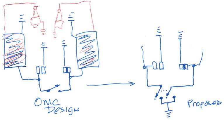
Question 3: Proposal: If I were to change to a 2-pole switch, per the schematic below (on the right), I would be shorting the points together *AND* guarantee grounding them as well. Seems to me this is a “belts & suspenders” approach that must work.
Having a fully-functional “panic button” kill switch on the boat’s dash would be nice. (indeed, I thought the stock wiring provided such!). I’m curious to hear your thoughts.
June 27, 2024 at 12:20 pm #288671a ground is a ground sourced of the dormant points or on the engine frame it is still a ground and should stop the engine..
did you ohm out your ground.. any chance the mag plate is floating and needs a flexible ground strap.
when did all this start anyway…did you work on ignition and now have this problem ? gap set ok ?
Joining AOMCI has priviledges 🙂
June 27, 2024 at 1:10 pm #288673The mag plate is well grounded. I’ve checked that a bunch. I get zero ohms from between any two metal surfaces anywhere on this engine.
This didn’t just start happening; it’s been this way (couple of years) ever since I “built” this engine (it was pieces & parts from 3 carcass engines). At first I thought it might be in the wiring from the engine to the dashboard (via a Deutsch connector), but in a “bucket run” I did it locally with a temporary switch on the engine. Same result.
I’m going to re-configure with a double pole switch per my proposed schematic above…as I said, “belts & suspenders”. Still, it’s hard to come to grips with why this is happening when wired in a “stock” configuration. It just doesn’t make a lot of sense (to me, at least).
FWIW (if anything): I may not be an outboard engine expert, but I’m an EE with 40+ years of power & control circuitry knowledge under my belt. Engine schematics & this circuit in particular are not complex to me…which is why I’m perplexed. That said, if I’m missing something, I’m open to all suggestions.
June 27, 2024 at 3:55 pm #288674Well, I have no idea what this would happen either. Am guessing this is a universal mag engine, not the low tension ignition or mad distributor set up on the old V4s.
I am reading that you connected a switch directly at the engine and it did the same thing. You are using some sort of toggle switch, correct? Do you have any pictures of the mag plate wiring? Perhaps there is a break in the wiring underneath the mag plate somehow occurring at higher RPMs. Perhaps this toggle switch has a high resistance over the terminals, you might try rigging up a conventional OMC push button set up to see what happens.
In any event, I don’t see any reason why your proposed setup would not work, but primary voltage arcing could be a concern….
June 27, 2024 at 5:30 pm #288678Easy. (Maybe). Ill bet you have a 35-40hp right? It. Has a vacuum cutout switch, right? Ill bet you have the vacuum cutout switch wired incorrectly?
Wire from upper set of points goes directly to the kill switch. Wire from lower set of points goes to the center terminal of the vacuum cutout switch.and the other side of the kill switch goes to that same center terminal.
Finally,the body of the vacuum switch is grounded through either a mercury switch or a micro switch under the mag plate.
My guess is that you have your kill s switch wire connected to the mercury or micro switch instead of to the center terminal/other set of points. Or some variation of the above.
June 28, 2024 at 12:21 am #288684maybe…. you have a break in your ground wires used for killing the engine. I know you indicated they tested 0 ohms but check any flex points
see if you can ohm out the wires (engine not running) while throtling up and down to move the plate.
bending/flexing wires can break eventually . Here is a typical flex brake on HV wires to spark plugs … it happens !
Joining AOMCI has priviledges 🙂
June 29, 2024 at 12:16 pm #288741Easy. (Maybe). Ill bet you have a 35-40hp right? It. Has a vacuum cutout switch, right? Ill bet you have the vacuum cutout switch wired incorrectly?
Wire from upper set of points goes directly to the kill switch. Wire from lower set of points goes to the center terminal of the vacuum cutout switch.and the other side of the kill switch goes to that same center terminal.
Finally,the body of the vacuum switch is grounded through either a mercury switch or a micro switch under the mag plate.
My guess is that you have your kill s switch wire connected to the mercury or micro switch instead of to the center terminal/other set of points. Or some variation of the above.
Great point Frank, betting on this explanation for sure…
NJ: Does your engine have the vacuum switch set up??
July 1, 2024 at 1:58 pm #288771Vacuum switch – yes.
Wired incorrectly as described by frankr? – no.
The kill wires are electrically attached to the points. Yes, the vacuum switch is being used as a connection point….but to the center terminal (i.e. the same place the point is connected.). The kill wire is NOT connected to the mercury switch.
I’m at a loss on this one. Sure seems to me that electrically connecting these wires together (regardless of switch type or location of connection, etc.) should kill the engine immediately…and at low-to-medium RPMs it does. But at high revs?….nope. Yes, the engine sputters badly, but with the points tied together (and at least one point grounded at any moment on a revolution), creating a spark should be impossible.
July 1, 2024 at 4:22 pm #288772Well, I’m not an EE but I have enough electronics training (radio/TV repair) to figure this thing out. But it beats me. There is something going on here that we aren’t seeing. Something like the wrong flywheel, for instance.
Before I spend another couple of hours trying to figure out what that “something” is. Let’s start over with some information as to what we are working on. Exactly what year and horsepower motor? Does it have the OMC Universal Magneto or does it have the OMC Low Tension magneto? Certainly not the Battery CD with points, I hope.
July 1, 2024 at 4:41 pm #288773Btw wrong flywheel may not be a crazy guess.Any bets?
-
AuthorPosts
- You must be logged in to reply to this topic.


