Home › Forum › Ask A Member › Elto 1940 Handitwin
- This topic has 8 replies, 2 voices, and was last updated 8 months, 1 week ago by
 T….in Wisconsin.
-
AuthorPosts
-
July 8, 2016 at 2:36 am #4696
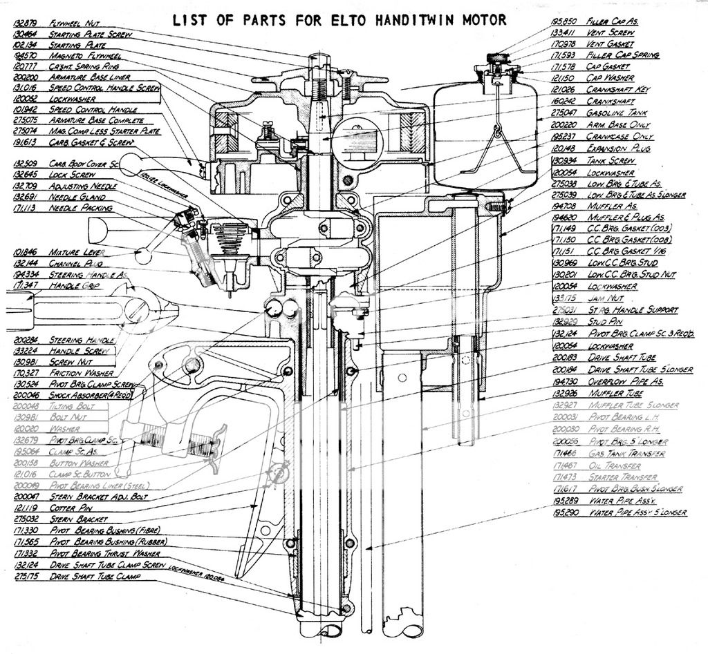
I just bought a 4357 Elto and need to know how the tiller assy hooks up to the power head? mine is riding on 4 ball bearings but will not turn but the carry handle will turn the lower unit. I paid $ 75.00 for the motor it’s all there except the tiller is broken off above the elbow and replaced with a tiller arm bolted on to the stub. I hope this makes sense and what parts do I need to bring the lady back to her former self? Thanks
July 9, 2016 at 10:57 pm #39949July 10, 2016 at 12:10 am #39951Thanks Kevinf
I got the tiller to turn after taking apart the tiller and putting the ball bearings back in the right place. The diagram helps a lot , I guess it is all there minus the tiller assy. The one I have is broken off between the handle screw and the power head , they screwed on a replacement tiller handle to the broken piece. I think this a neat motor in good shape I have 2 other elto pals I like very much Thanks againJuly 10, 2016 at 1:14 am #39957Elto built 4000 Handitwins in 1940. Models with serial numbers of 4001 and higher were built in 1941. 1942 production was stopped by the start of World War Two. It is a two cylinder apposed motor with a bore of 1-¾" and a stroke of 1-⅜" for a piston displacement or 6.07 cubic inches. It’s 3 horse power is rated at 3,500 RPM. The fuel tank holds 3-½ pints and will run the engine upwards to an hour depending on load. It is water cooled by an aluminum veined two stage centripetal pump at the top of the gearcase. It weighs 31 & ½ pounds and sold for $68.50 FOB Milwaukee Wisconsin in 1940.
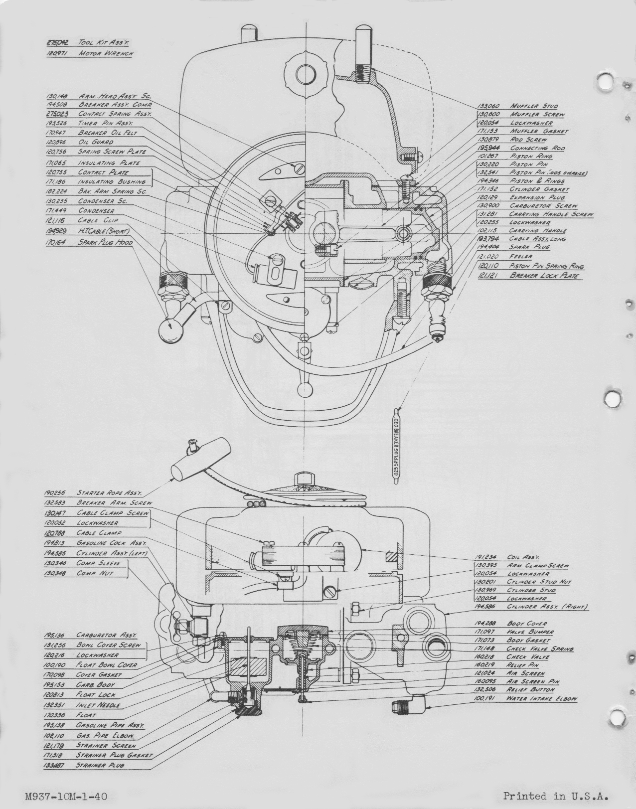
The powerhead is floated on the 4 rubber balls (200048) to absorb vibration. (Dad bought a bunch as non-lethal sling shot ammunition to ward off unwanted animals in our yard. They were very effective.) They nest in 4 sockets in the steering handle support bracket. The steering friction is adjusted by the 132124 pivot bearing clamp screws. It should be just tight enough to keep the outboard on course. The recommended Champion C-7 spark plugs have been replaced by Champion 516 gapped at .025". The breaker points are set at .020"
The carburetor check valve lift should be 9/64" – valve spring pressure should be 3 ounces – Fuel level in the float bowl should be 13/16" down from the rim when held level. . . . 😀

 March 19, 2024 at 10:06 am #286036
I have a 41 Handitwin 4537 01639.
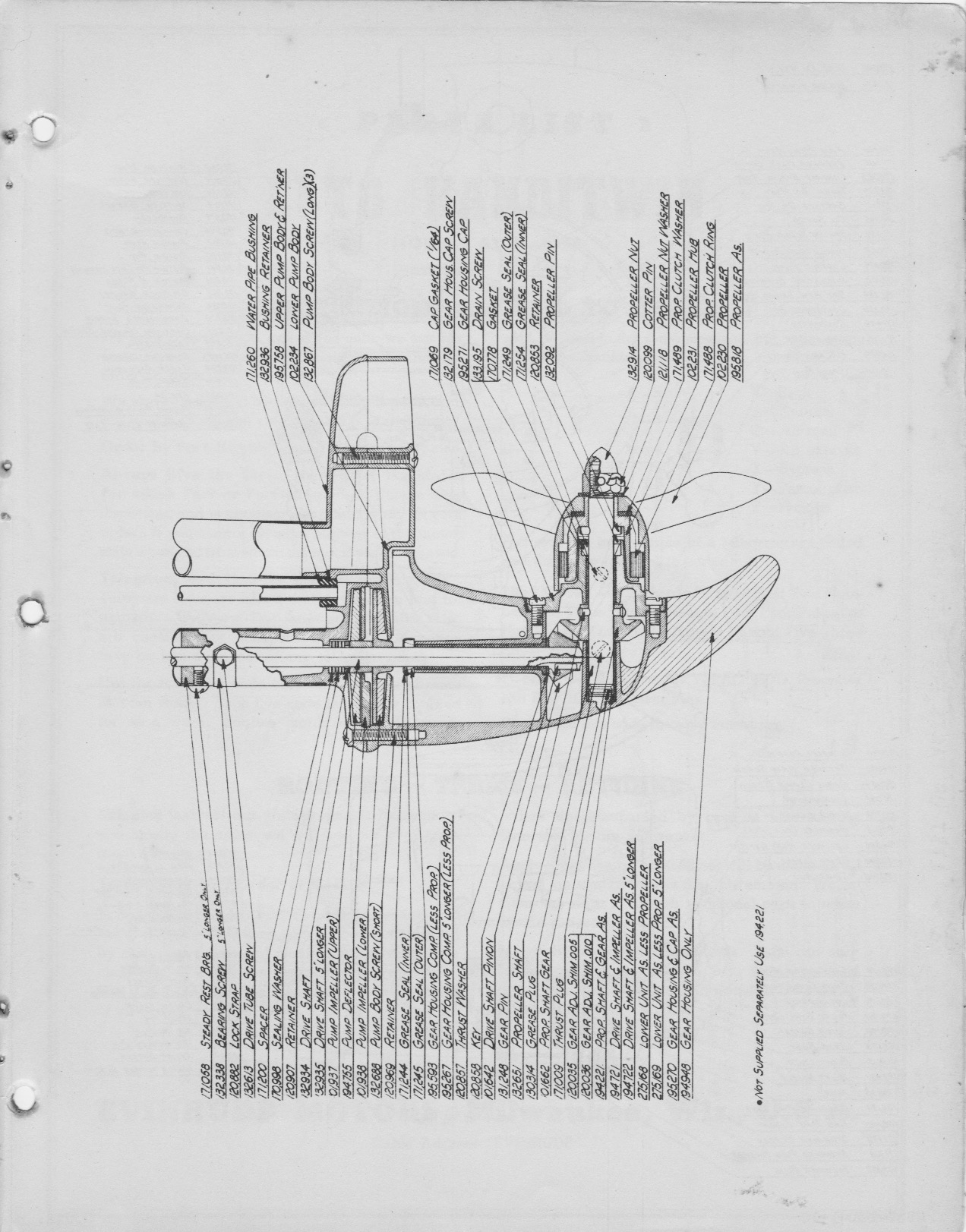
Were the gear adjustment 120035 & 120036 shims used in all the units. I didn’t find any when I took it apart to inspect & grease.
T..
March 19, 2024 at 5:29 pm #286043It most likely had a shim in one place or the other, or both when new,
but I guess I’d check the backlash and go from there.Prepare to be boarded!
March 20, 2024 at 9:55 am #286053Yes, that’s sound logic being both shims are shown on the parts diagram.
Upon closer inspection I didn’t see a thrust plug either.
Backlash measured with a feeler gauge (best I could do) is roughly .032″. The prop shaft gear stand proud of the mating gear housing by approximately .085″.
Given current backlash adding shiming would result in less engagement and increased backlash. At this point would it still be a good idea to insert a thrust plug slightly longer than the .085″ clearance dimension for the end of the prop shaft to interface with?
T..
March 20, 2024 at 12:12 pm #286057In looking at the parts diagram, it looks like if you made the
thrust plug longer, that it would push the prop shaft, and
hence driven gear, further away from the drive gear, and
ending up in “more” backlash. Then again, without
the actual parts in front of me, I’m just guessing.My little bit of automotive training almost 50 years ago,
taught us to use bluing grease on the pinion and differential
gears, rotating them, to check the actual gear mesh, making
sure the gears were meshing near full depth and in the
centers of the teeth.On the lower horse power motors, I pretty much go by “feel”
when checking the backlash, but none of my motors
see much use.Prepare to be boarded!
1 user thanked author for this post.
March 20, 2024 at 1:18 pm #286059Agreed, my thought of adding a thrush plug was to serve as a bearing surface to the prop shaft. In effect it would still push the prop shaft and drive gear out even if only by a few.001’s thus slightly increasing the backlash.
Regardless, at this point and given its current state I don’t see that installing a thrust plug to provide a bearing surface for the prop shaft holds much value.
Motor is intended to be an occasional runner and for display.
I’ll post a follow up of the barrell test later.
Thanks for your thoughts in helping me think this through.
T..
-
AuthorPosts
- You must be logged in to reply to this topic.


