Home › Forum › Ask A Member › 1929 Johnson Model J-25 Plug Wire
- This topic has 15 replies, 4 voices, and was last updated 3 years ago by
 Tubs.
Tubs.
-
AuthorPosts
-
May 1, 2022 at 6:30 pm #259274
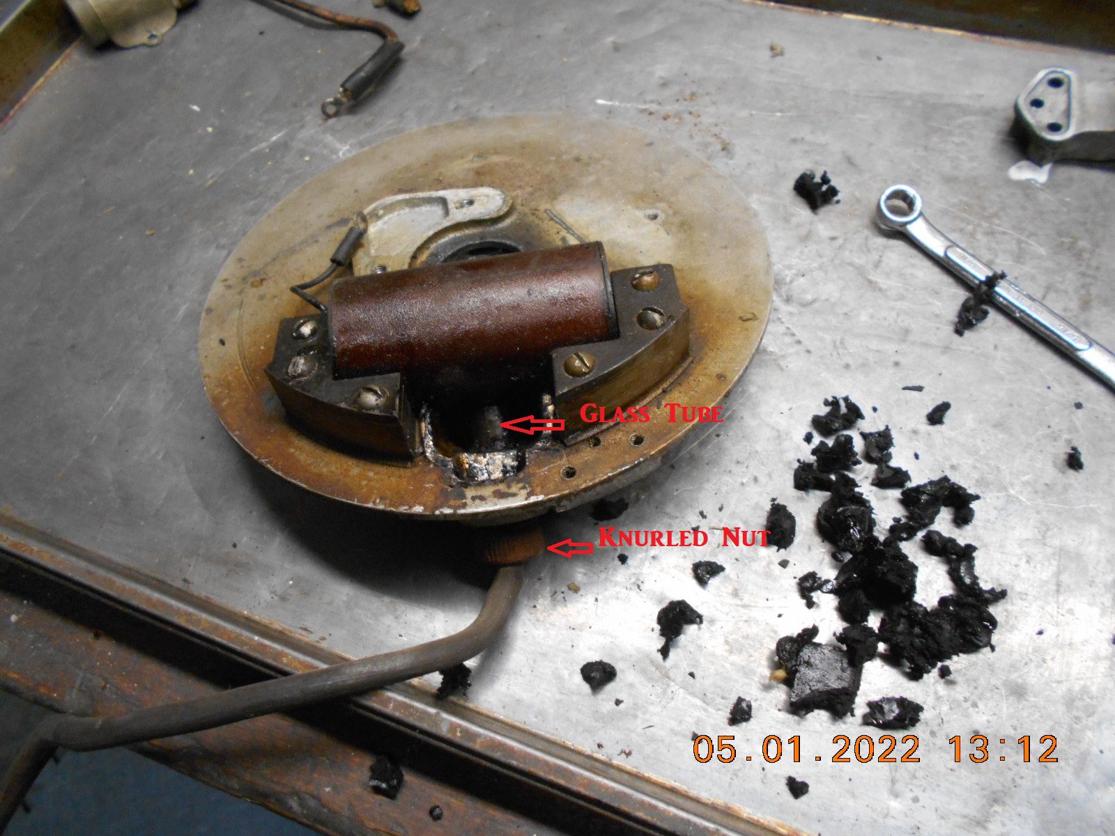
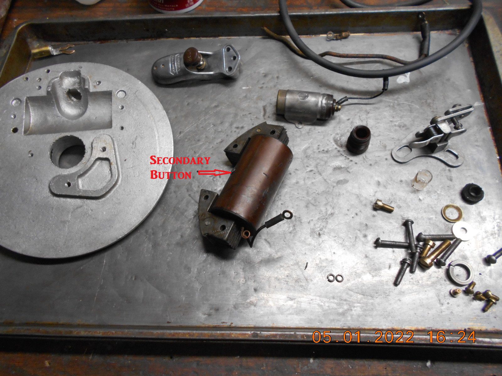
I pulled the magneto apart today on the subject motor.
It has the plug wire going into the bottom of the mag plate
through a knurled bakelite nut and glass tube. It was still
potted in tar. Unsure if it’s been apart before or not, but
the knurl on the nut looks a little chewed up, and there’s
a little chunk broke out of one end of the glass tube.
Possible I broke it. Also, I found no spring as Tubs described
in a prior post (below) He references a photo of “how” he
put his back together, but said photo is no longer on the thread.To Tubs, or anyone, what’s the best way to attach a new coil wire?
Similar to original, or try to solder it to the secondary button?
The old plug wire that was in it had the end of the inner core bent
over, touching the secondary button on the coil. I’m not sure
if mine is suppose to have a spring, and if so, just how it worked.+++++++++++++++++++++++
1924 Johnson Mod B
Post #252911First challenge is the remove the wire nuts.
They are easily broken and difficult to replace.
Second, you’ll find that where the wires connect to the coil is
sealed with Tar. A heat gun will soften the tar enough so that
you can remove the coil. Originally the connection is made
with springs inside glass tubes. Most people don’t notice those
parts were even in there as they get lost in the tar when removing
it. Kerosene works as well as anything to clean up the parts.
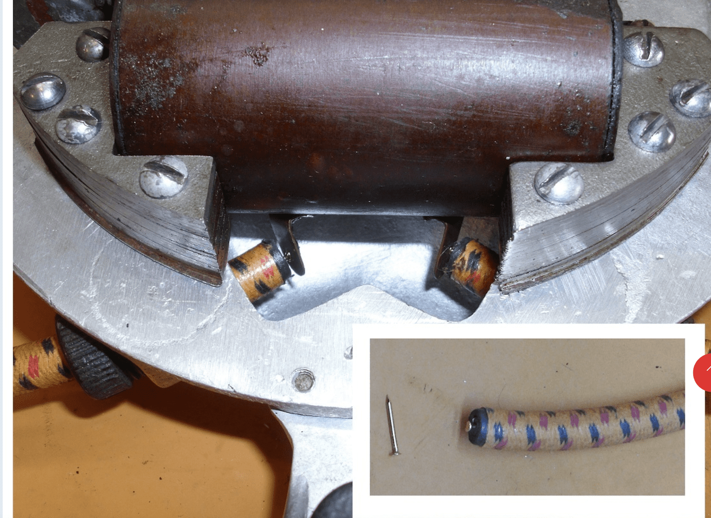
Picture shows how I connect the new wires. I don’t think too
many people replace the tar once its removed.
Tubs============
My J-25 MagnetoPrepare to be boarded!
May 1, 2022 at 9:30 pm #259282I think this is the picture of the “alternate” attachment that Tubs had posted.
Tubs – no copyright infringement intended!
Bob
1937 Champion D2C Deluxe Lite Twin
1954 Johnson CD-11
1955 Johnson QD-16
1957 Evinrude Fastwin 18
1958 Johnson QD-19
1958 Johnson FD-12
1959 Johnson QD-20“Every 20 minute job is only a broken bolt away from a 3-day project.”
"Every time you remove a broken or seized bolt an angel gets his wings."May 1, 2022 at 9:42 pm #259288Thanks Bob. That’s a slightly different beast, being a twin cylinder.
I just searched “glass tube” and that post came up.Prepare to be boarded!
May 2, 2022 at 9:13 am #259305
Thanks Bob for providing that for Tom.
I did both an A and a A-25 that like that
and it seem to work OK. That little spring
is easy to miss. I’m electrically challenged
and have no understanding of how any
electrical component functions. For those
that are knowledgeable, what could be the
purpose of this little spring to make the
connection? Its quite a bit smaller than the
plug wire. Could this be some Flintstone
attempt at a resistor to increase the spark
at the plug. It doesn’t make sense to me
but those folks were way smarter than
they often get credit for so I’m sure they
had a reason. Your thoughts?
Tubs.A "Boathouse Repair" is one that done without having tools or the skills to do it properly.
-
This reply was modified 3 years ago by
 Tubs.
Tubs.
May 2, 2022 at 9:24 am #259307Thanks for posting that spring tubs. I’ll dig around the waste tar a little
to see if the baby (spring) got thrown out with the bath water.The spring looks like an attempt to insure electrical contact with the
secondary button. You wouldn’t think it would hold up, or be too effective,
but I did have continuity with the ohm meter from the plug terminal
to the windings, before I tore it apart.
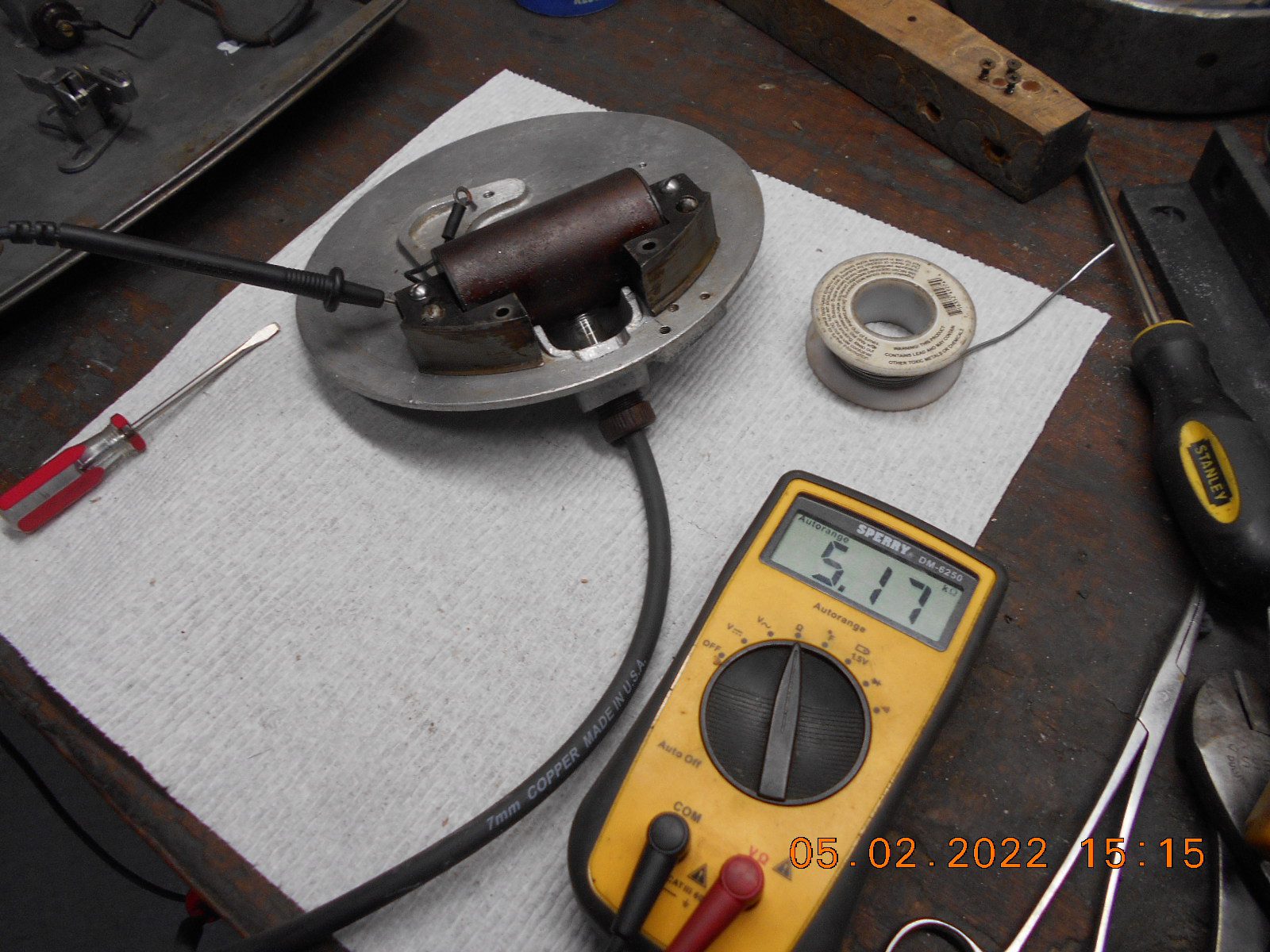
FYI for anyone whose curious, The primary ohms on the coil were .1 K, secondary 5.2K.Perhaps I’ll solder a brass tab onto the secondary button and attach the plug wire
like you did. Seems to me I may have done something similar on an A-45 or similar motor.Prepare to be boarded!
May 2, 2022 at 9:37 am #259308
I didn’t use any solder. Just have tension against
the tabs on the coil. Thought I might put the tubes
and springs back in one day but that motor has
moved on. Soldering probably would have been a
good idea seeing that the tubes and springs didn’t
return.
Tubs.A "Boathouse Repair" is one that done without having tools or the skills to do it properly.
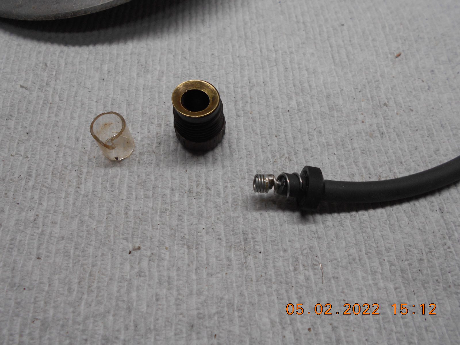
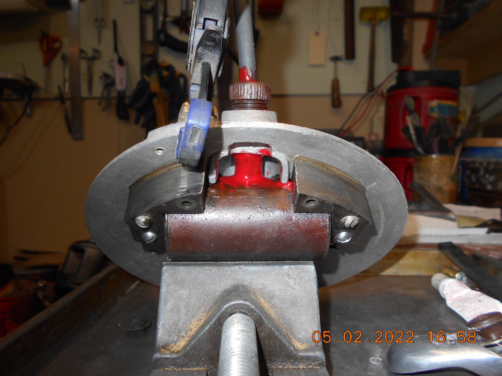
May 2, 2022 at 7:51 pm #259327I opted to install the new plug wire similar to the original setup,
with a few changes.I never found the old contact spring, but assume there was one there.
I dug through my stash of springs and altered a compression spring to fit.
I later trimmed the outboard end of the spring shorter than the photo,
as I was afraid it could arc on the mag plate.I soldered the end of the plug wire to the spring.
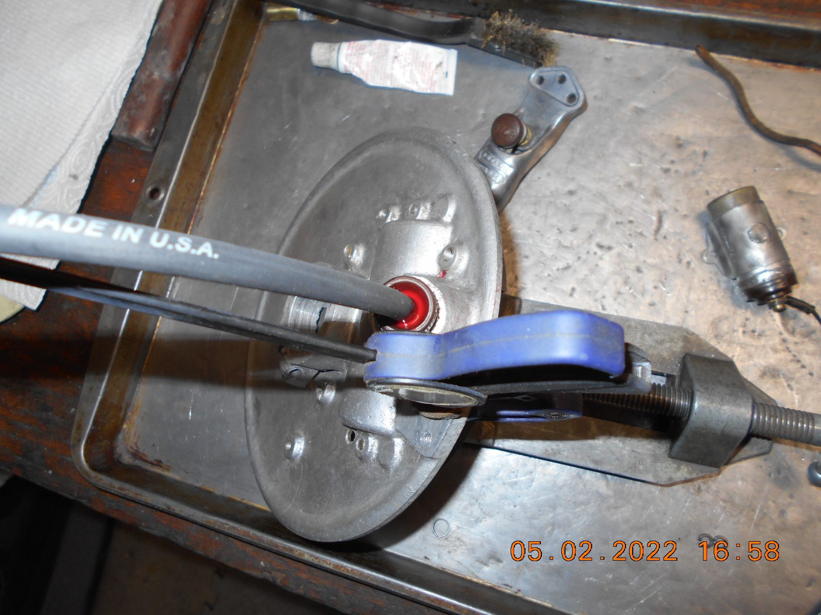
The old rubber bushing under the knurled nut was shot, so I made one
that seem to work good, out of an old style, hard rubber faucet washer,
that already had the correct taper to fit in the knurled nut correctly.
I had to drill the hole in the rubber washer out bigger, to 9/32″, so the
plug wire was a snug fit inside of the washer. When the knurled nut is
tightened down, it seem to hold the wire fixed tightly in position.I wrapped electrical tape around the spring (inside of the original glass
insulating tube), leaving the end of the spring bare, as to contact the
secondary button on the coil. Before installing it, I put a generous amount
of silicone grease on the secondary button and inside of the spring,
to prevent corrosion. For extra luck, I used some liquid tape around each
end of the glass tube to help keep moister out, and put some around the
plug wire inside of the knurled nut.After all said and done, I rechecked the ohms, and got the same reading as
in the one photo.
Time will tell if it’s successful…… but then again, I’m not even sure it’s going to have
enough compression to be a runner.Prepare to be boarded!
May 2, 2022 at 9:47 pm #259348Looks like a very good fix. Let us know how it goes when you run the first test fire.
Bob
1937 Champion D2C Deluxe Lite Twin
1954 Johnson CD-11
1955 Johnson QD-16
1957 Evinrude Fastwin 18
1958 Johnson QD-19
1958 Johnson FD-12
1959 Johnson QD-20“Every 20 minute job is only a broken bolt away from a 3-day project.”
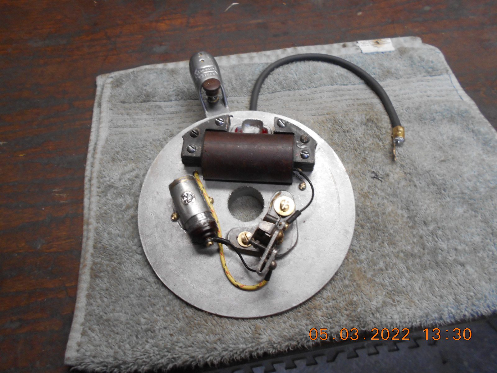
"Every time you remove a broken or seized bolt an angel gets his wings."May 3, 2022 at 5:39 pm #259380I finished up the magneto today….. I hope.
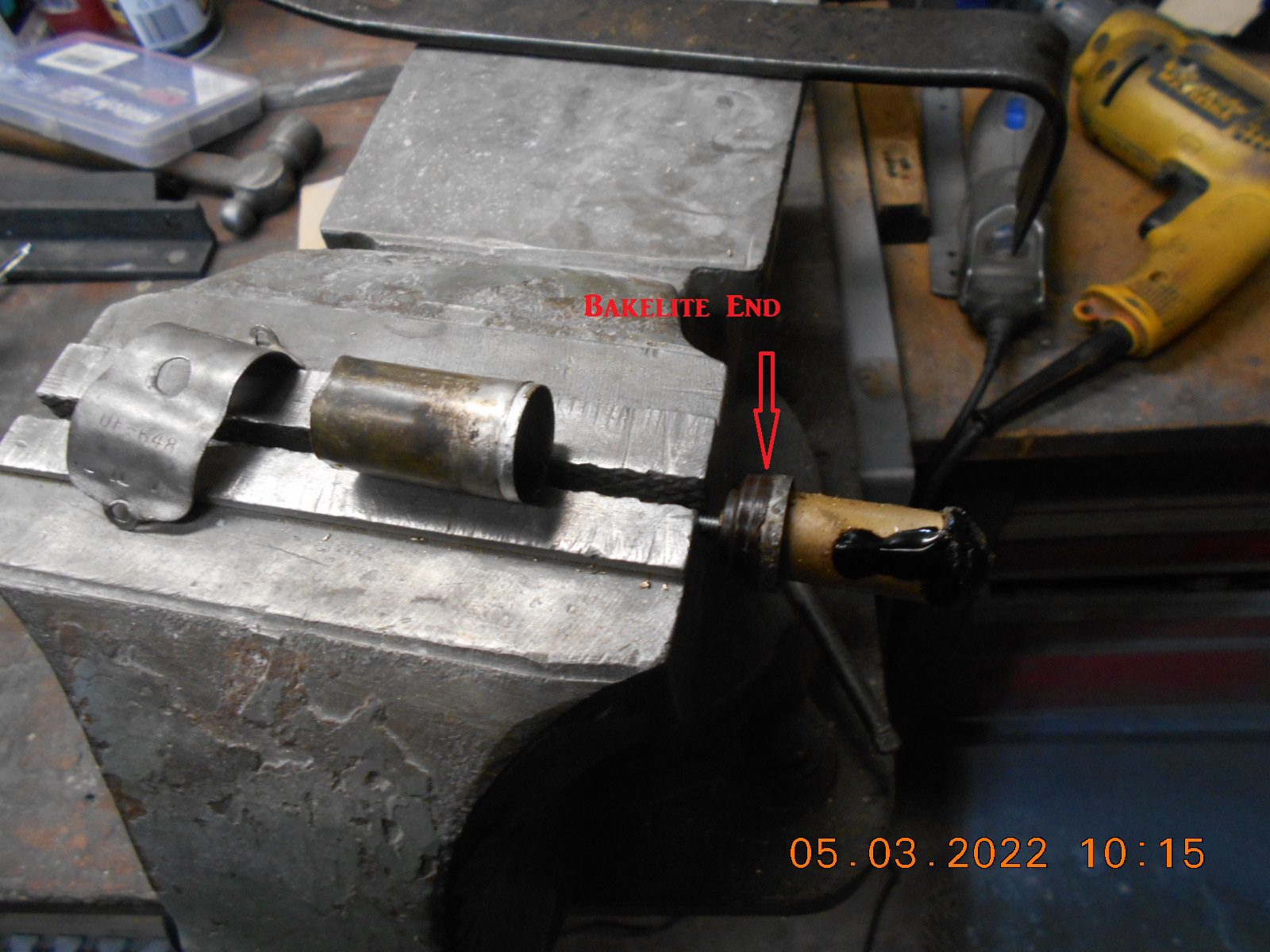
I tore apart the old condenser can. If I had this one
to do over, I would not have cut the back end of the can off
with the Dremel. Once I had the end opened up, I was not
able to extract the guts, as there’s a solid 1/4″ brass round stock
going down the entire center length of the condenser.
The Bakelite & brass business end that has the terminal was soldered
to the can. Ended up heating up the can with the little torch and pulled
it apart, with no apparent damage to the Bakelite.
Then was able to hacksaw the guts off close to the terminal end and finish
removing the guts.
A tiny hole was drilled along side of the brass terminal threaded hole,
for the .1 mfd capacitor wire to run thru.
Another small hole was drilled thru the condenser can end that I cut off,
for the other capacitor lead to exit and be soldered to the can as a ground.
Not as pretty as I hoped, but hopefully it works.
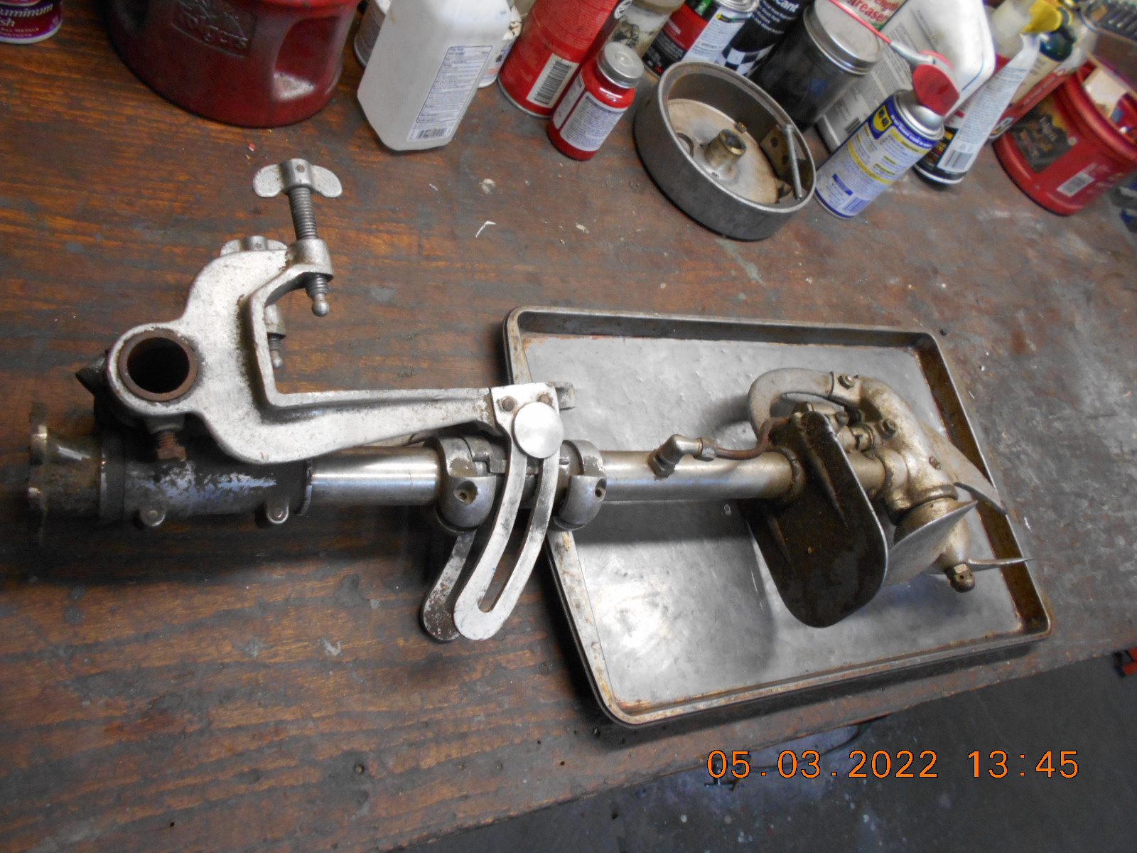
I started on the lower unit next. From external appearances, it appeared
to be in good shape.
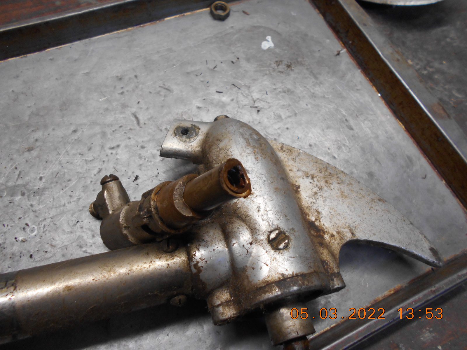
I’m not sure how well it pumped water last time run, but pretty sure
the water pump piston spring should not be seen in this photo.
What can I make a new piston out of?
Prepare to be boarded!
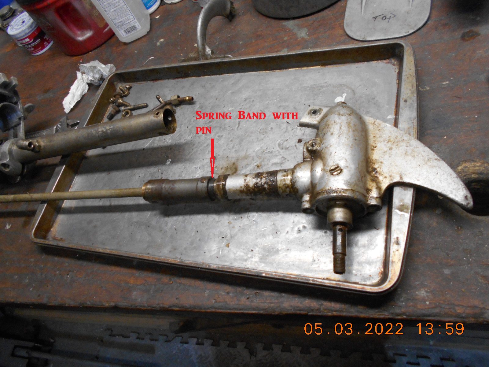
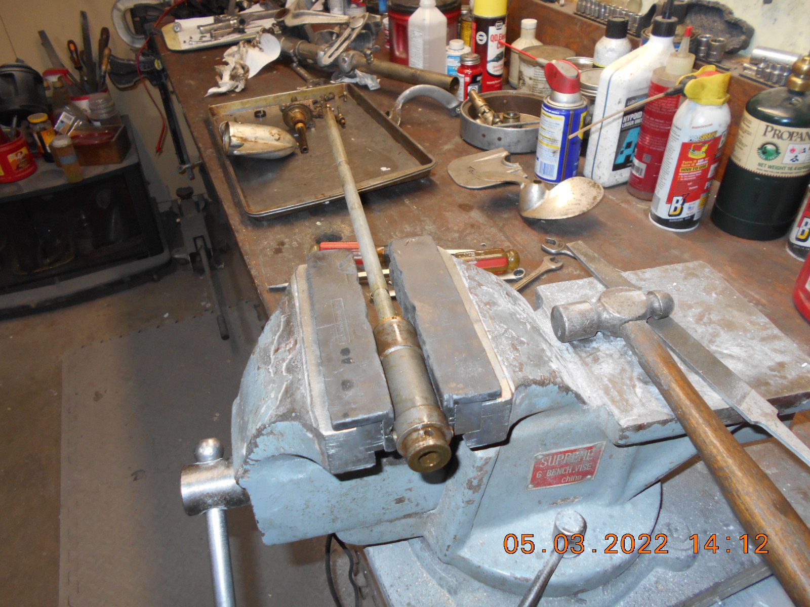
May 3, 2022 at 6:11 pm #259386After I separated the driveshaft tube from the gear case I tried to get
the driveshaft removed from the gear case. There’s a coupler on
the driveshaft with two visible drive pins in it.
As I attempted to remove the lower “big” pin on the end of the coupler,
(without any success), I noticed a “spring band” just below, and
another drive pin underneath the band. This is apparently the
correct way to remove the drive shaft.
I’ll have to inspect the driveshaft with coupler for “trueness”, as
it almost seems that there’s a wobble when spun over by hand.
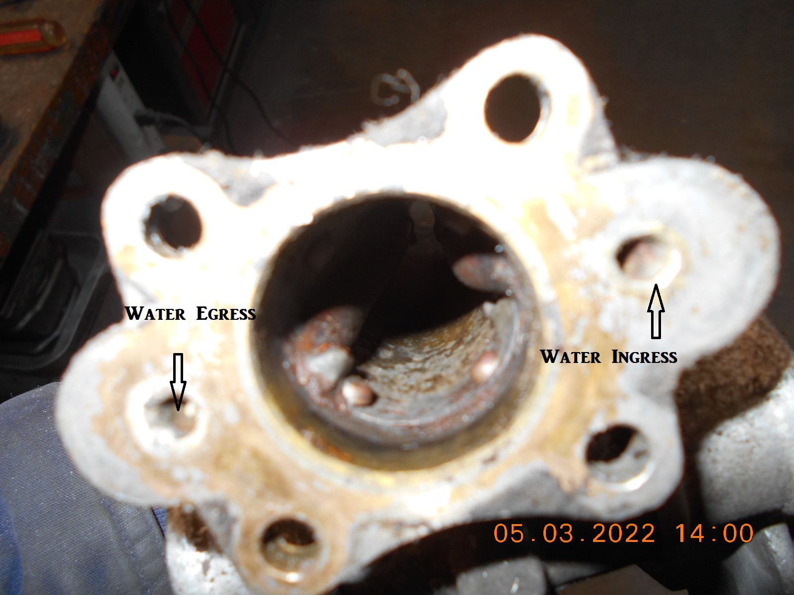
Looking down the driveshaft tube at the powerhead mount flange,
there’s two water lines inside the tube, both plumbed to the flange,
and hence the powerhead.
The feed tube connects to the piston pump, via an external tubing.
The outlet tube shoots out the side of the driveshaft tube, above the
water line.
All I know for today.
Prepare to be boarded!
-
This reply was modified 3 years ago by
-
AuthorPosts
- You must be logged in to reply to this topic.


