Home › Forum › Ask A Member › 1936 Champion 1B info
- This topic has 4 replies, 3 voices, and was last updated 1 day, 2 hours ago by
bigbinkerflux.
-
AuthorPosts
-
March 29, 2025 at 9:37 pm #294975
- I note there is no adjustment on the nose of the gearcase for setting the gear lash. Therefore, is it done by using a Bakelite or such washer inserted ahead of the prop shaft going into the gearcase nose, or perhaps a washer ahead of the rear bearing bushing? The latter would seem to make more sense from a service standpoint.
- What is the approximate location of the drain/filler plug? My gearcase was a basket case that was reworked with welding, etc. Did it use a 1/8″ brass pipe plug? I assume it vents through one of the mounting bolts when filling?
- Finally, there is a small cast-in hole located just below the anti-cavitation plate on the port side of the gearcase; it is very close to one of the mounting bolts. It leads nowhere because of the brass tower housing blocking it. Is that correct?
Thanks, Ron Vaughan Sr. Sea King Special Interest Group leader.
March 30, 2025 at 12:19 pm #294997
Ron, I’ve never had a 1B. Came close last fall. It was cheap enough but it was in just terrible condition. Here are some pictures from my files of a later model. They may be of some help as far as what goes where and what is correct. Also a link to a video Lincoln Davis posted on the model you may fine interesting. https://youtu.be/d7IbC0GMKKg?si=_7QZVL4NEEKuSdn_
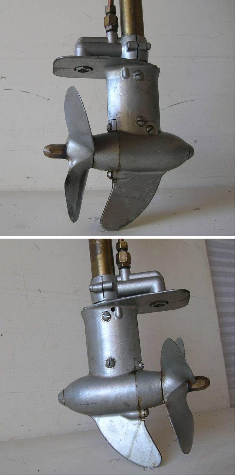
A "Boathouse Repair" is one that done without having tools or the skills to do it properly.
March 30, 2025 at 1:02 pm #295002Hi Tubs,
After taking a second look and doing some experimenting, I believe the answer to adjusting the gear lash is accomplished by merely using gaskets of varying thickness between the surfaces of the rear bushing flange and the gearcase itself. (Your motor has a different rear bearing carrier.)
Somehow, I overlooked the 1/8″ pipe plug that is clearly visible in your excellent photo. Blame it on old age! But is it supposed to be the filler plug, and therefore is one of the mounting bolts indeed to be used as a vent as I wondered? That would make sense, but because of the location of that plug, you could never drain off any water that would gather at the very bottom of the gearcase or drain the old grease very well.
I should mention that the previous unknown owner had mounted a homemade steel skeg using four big bolts to replace the snapped off skeg. It appears that he may have used an existing drain plug hole. Hence my question as to where a drain/filler hole may have been.
I see your motor also has that small hole just below the anti-cavitation plate. I wonder, if you poke something into it, will it hit the downtube and stop?
Many thanks for your reply. We’ll see what others may have to say about this.
Ron
March 30, 2025 at 6:45 pm #295011Ron – yes, the pipe plug on the side of the gearcase is the fill port and the top mounting screw for the rear gearcase cover is the vent plug. Tubs picture is identical to my 1937 Champion D2C gearcase. And yes, if you poke something into that small hole below the cavitation plate, it just hits the driveshaft down tube – I’m not sure of the purpose of that hole.
Bob
1937 Champion D2C Deluxe Lite Twin
1954 Johnson CD-11
1955 Johnson QD-16
1957 Evinrude Fastwin 18
1958 Johnson QD-19
1958 Johnson FD-12
1959 Johnson QD-20“Every 20 minute job is only a broken bolt away from a 3-day project.”
"Every time you remove a broken or seized bolt an angel gets his wings."March 31, 2025 at 12:00 pm #295048Thanks Bob. Interesting info. I’m beginning to wonder about some things on my motor which might suggest that a couple of the parts may have been changed (despite it appearing original), or if it was maybe the result of a temporary parts shortage at the factory. 1. The clamp bracket isn’t cast as one piece. Each clamp screw bracket is separate as used on the 1936 4.4 HP Light Twin. 2. The spark lever and kill button location looks the same as the one used on the 1936 7.6 HP Heavy Twin. Note: The images for this info came to me third hand via a very reputable source who had access to them from an old-timer who put them together several years ago from factory brochures.
There is one final clue which may or may not be of significance. The model (1B) and serial number which is stamped into the crankcase and located underneath the tiller handle mount has the letter “B” stamped backwards! Hmm….could that possibly be a clue that signifies the motor is an interim model, and therefore a dealer should note it when ordering parts?
When I get this critter all together and get my camera working, I will post some photos. Might make an interesting article for the Outboarder.
-
AuthorPosts
- You must be logged in to reply to this topic.