Home › Forum › Ask A Member › 1948 Gale Hiawatha 5HP
- This topic has 51 replies, 8 voices, and was last updated 3 years, 6 months ago by
 frankr.
-
AuthorPosts
-
July 26, 2020 at 4:13 pm #209961
I am tracing a water cooling problem with my 1948 Gale Hiawatha 5HP
Model # 840MI25-7972A
I could not see any water coming out anywhere and the head was getting hot. Where do you look for water coming out. I see a small tube under the head with a 1/16 maybe 1/8 inch opening. What does that do? Is it for exhaust back pressure? I thought water would come spitting out of the slit in the lower unit but it does not look like it’s connected to anything. It’s just a cavity with a slit.
It looks like all the water goes through the head and just goes out the exhaust port below water. Mid so how do you know it’s circulating water?
I am purchasing a new rubber eccentric pump from Brian Wilcox. A member here of the club I’m sure everyone knows. It almost looks like mine had shrunk some vs being swelled from grease. Either way, The new pump should help.
Does anyone have a line on the two gaskets that attach to the bottom of the head and the cooling circulation plate?
I traced the coolant paths from the pump up to the 90 degree bend that enters the rotation tube for the motor. Then up that drilled passage Into the water circulation plate and gasket passage. Through a 9/16 round hole and up into the head. Then Through the head and Out a small rectangular opening back down into the circulation plate passages and into anotherrectangular opening and Finally into the center of the motor rotation tube that goes down to the underwater exhaust port.
I didn’t see in those paths where it connected to that small tube Below the head or the slit in the lower unit.
More pictures to follow.
July 26, 2020 at 4:21 pm #209967Here are two snap shots of the eccentric pump lobe moving counter clockwise from the left to the right and the space that is shown at each point to pump the water up.
It looks like too much space Left for good pumping action in the second photo.
July 26, 2020 at 4:39 pm #209972More photos with coolant flow directions.
July 27, 2020 at 12:53 am #210012That little tube is the crankcase puddle drain. There will be a bit of fuel dripping of of there but no water.
Water should haphazardly blow out of the exhaust relief slot about half way down the backside, in droplets. Most of it goes out the underwater exhaust outlet.
You did a pretty good job of tracing the water path. You did run some water through it, I imagine.
From where I sit, the pump looks surprisingly well.
So…I really don’t know where the trouble lies.
Gale warned not to remove the side covers from the powerhead, because they are very difficult to reseal. And they were right.
July 27, 2020 at 6:01 am #210020I recall that the water goes through the propeller into the pump. There should be holes that line up between the prop and the hub. If they don’t, no water gets to the pump.
Took prop off one of mine and found both holes on prop hub were blocked.-
This reply was modified 3 years, 8 months ago by
jcrigan.
July 28, 2020 at 8:49 pm #210196Does anyone know if gaskets are available or do I have to make them? What is the best material for this situation?
I did run water through the head and it was clear.
I will check the prop holes tonight and report back.
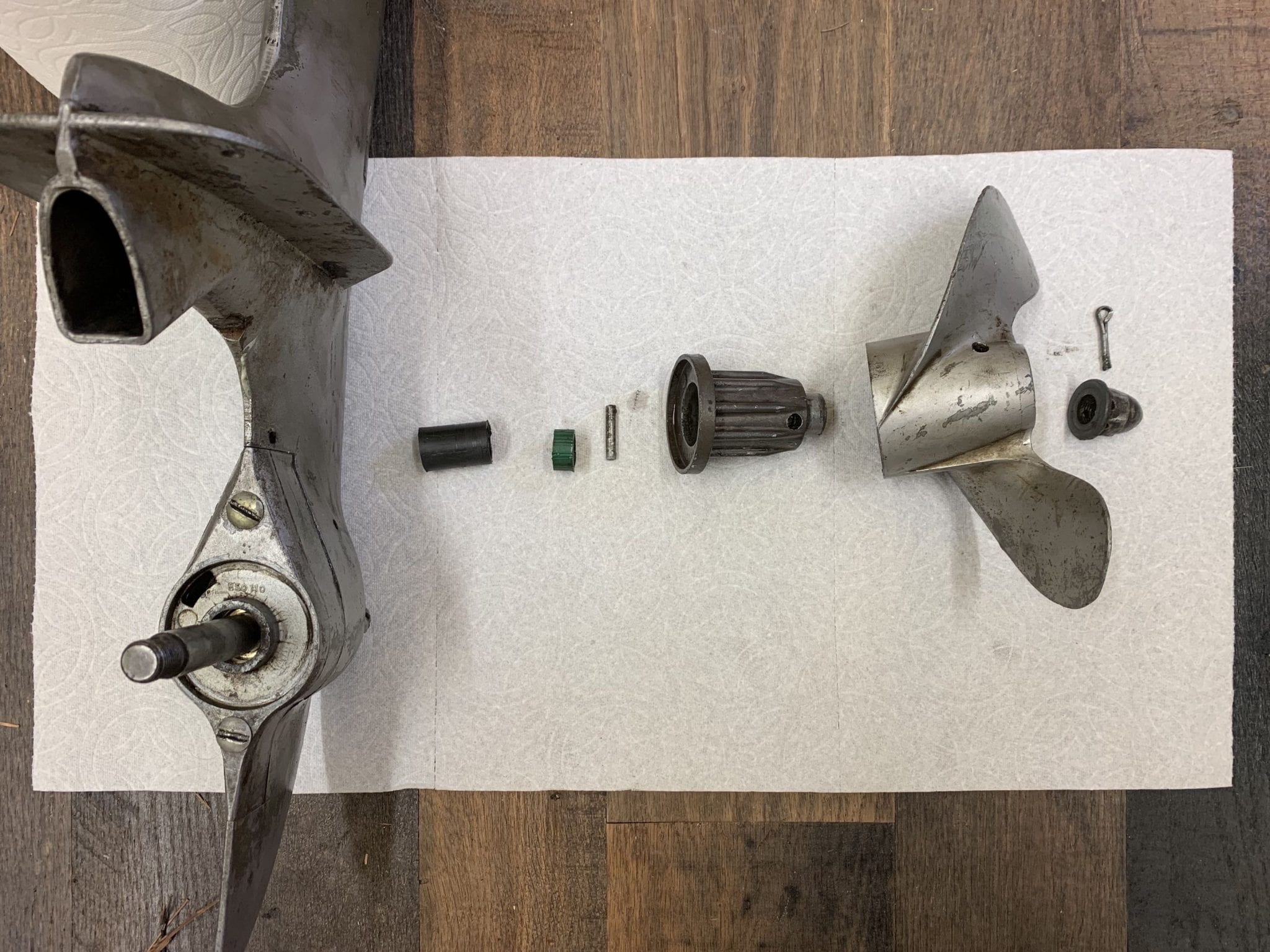
I have an odd piece on the prop shaft and I’ll try to get a picture of the parts stacked up while I inspect the prop.
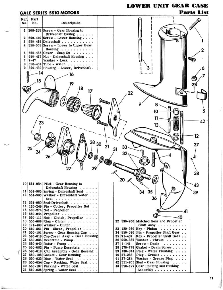
Does anyone have a good exploded parts picture or a real life picture of the parts stack in their motor?
Here is what I have from memory.
Cotter Pin
Prop Nut
Prop
(What is the removal process for the inner hub?)
Then I have a small green tube Like a rubber hose on the shaft.
Then a more ridgid spacer like piece
Finally the cover to the pump with the two screws and the seal.I’ll take a picture of what I take off tonight.
July 28, 2020 at 9:03 pm #210198Rubber hose???
This is a newer model, but should be the same as yours, I think.
 July 28, 2020 at 10:13 pm #210208
Wow, I have some extra parts! I can see that those extra parts are what was probably blocking the water flow.
One being the green hose looking tube and the other the Black hard plastic tube piece. Both were stacked and fit over the prop shaft. Weird that someone would do this.
Note: I did not take the rubber prop shock absorber out of the prop for this picture.
-
This reply was modified 3 years, 7 months ago by
 Mumbles.
July 29, 2020 at 12:01 am #210222Does anyone make the Clutch Ring #18 in the parts diagram?
July 29, 2020 at 6:28 am #210231Does anyone make the Clutch Ring #18 in the parts diagram?
marineengine.com has them in stock. 550089.
-
This reply was modified 3 years, 8 months ago by
-
AuthorPosts
- You must be logged in to reply to this topic.