Home › Forum › Ask A Member › 1956 Johnson 15HP Rod bearing clearance
- This topic has 25 replies, 6 voices, and was last updated 3 years, 3 months ago by
 Bob Wight.
-
AuthorPosts
-
December 29, 2021 at 3:22 pm #251901
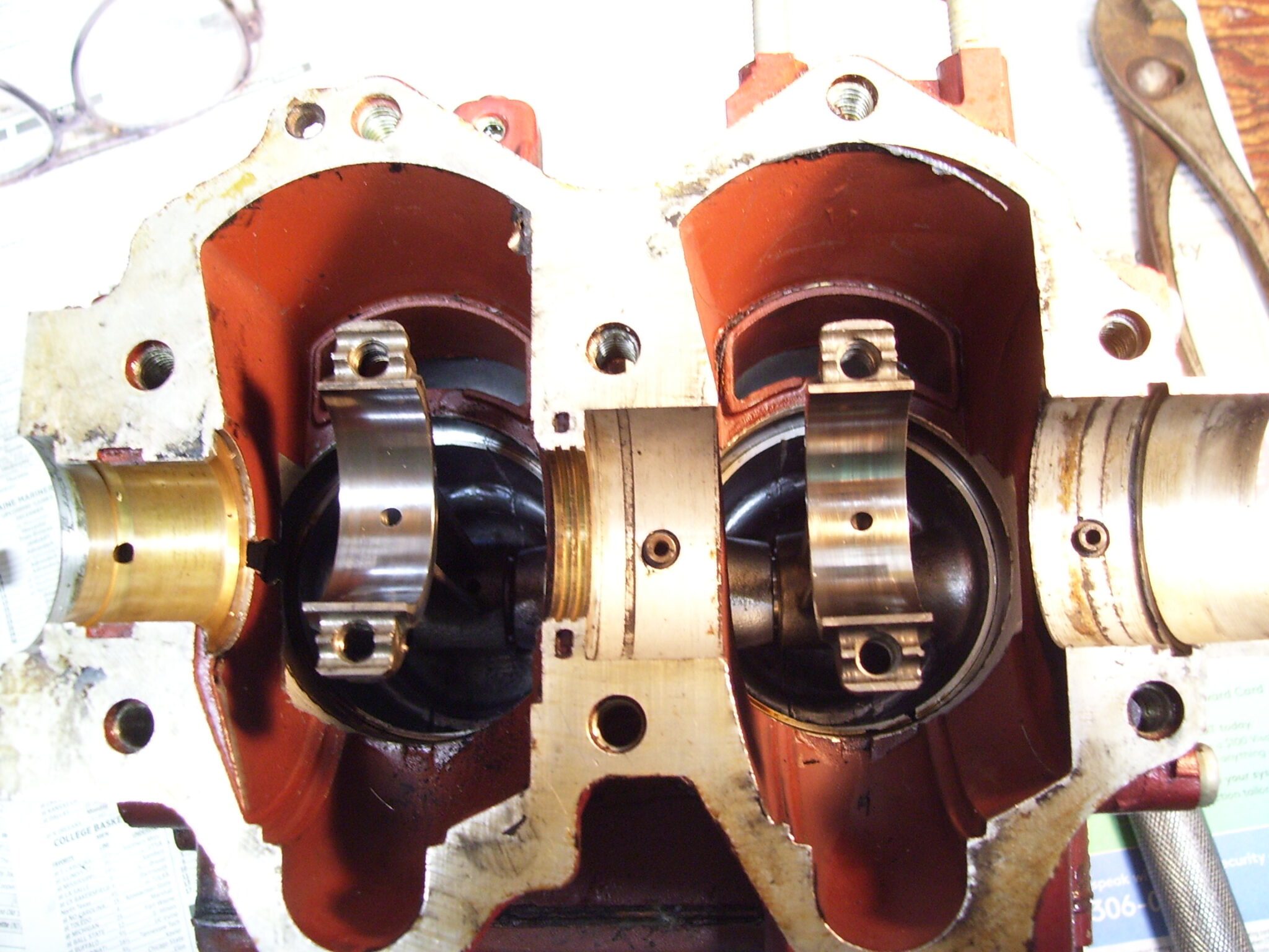
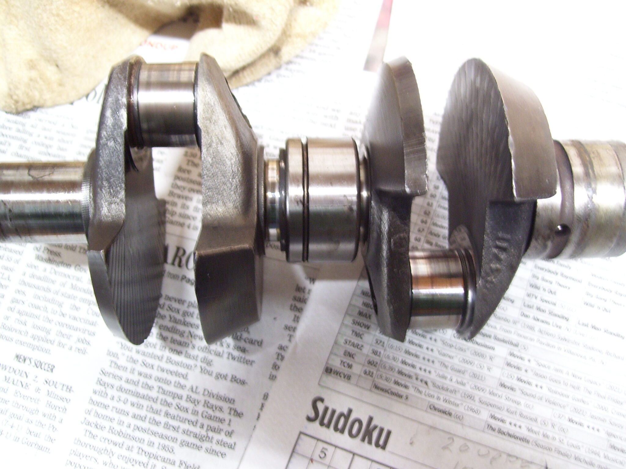
I noticed clearance in the rod bearings by doing a push test thru the spark plug holes. Opened the crankcase and the rod roller bearings at the crankshaft to try and get a reading on the clearance between the piston pin and the rod (sleeve) bearing. I could not set up a dial indicator so looked at a scale for reference and estimate the upper clearance at 0.020 inch and the lower at 0.010 inch.
Here are a couple of photos of the opened crankcase and the crankshaft. As you can see the bearing surfaces look fine.
I also have a couple of MOV file that show movement (looseness) of the flywheel/crankshaft without moving the pistons but the files ar 6 MB and too big to post here.
Where should I go from here? Replace rods? How much clearance is too much?
Thank you.December 29, 2021 at 4:33 pm #251905Typically the small end is worn not the crank end. It’s unscientific but see if you feel slop when you push and pull slightly on the rods now that you have them exposed.
December 29, 2021 at 4:45 pm #251906Steve,
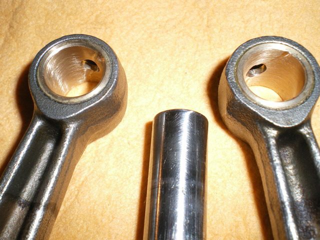
The clearance on the small end (piston pin to the small end sleeve bearing) is what I have been trying to measure by pushing and pulling on the roads as you suggest. I estimate 0.020 inch on the upper rod and 0.010 inch on the lower.
Thank you.December 29, 2021 at 4:50 pm #251907I have the same issue with a 10 hp. I am hoping a machine shop can press in a new bushing and ream it to the proper clearance. Replacement rods are unavailable for my application.
December 29, 2021 at 5:32 pm #251908To accurately determine the clearance, you have to put the caps back on the rods and measure the ID after torquing them down. Then the rod journal on the crank gets measured along with the diameter of the pins. The sum of the rod journal plus two pins subtracted from the ID of the rod will give you the running clearance.
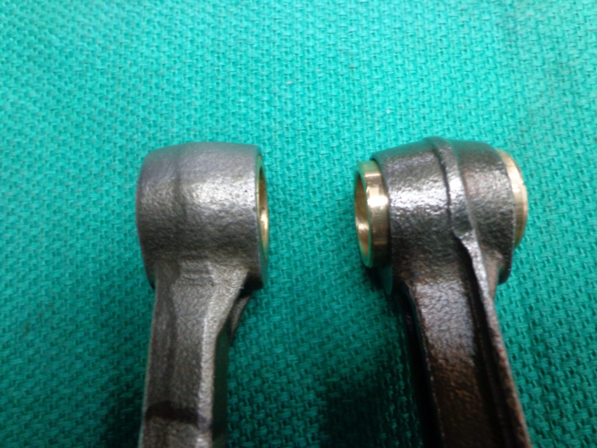
December 29, 2021 at 5:51 pm #251911The ’56 FD-10’s didn’t have needles on the rods small end but if the bushings are worn, they can be replaced.
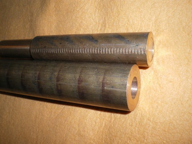
On these ten horse rods for example, I make the bushings out of 660 bronze and turn the ID slightly under size. After pressing them into the rods, I take them to a machine shop to get them honed to the final size. If you don’t have access to a lathe, you might be able to bribe a friend who has one to spin you some up with a case of brewskies.
December 29, 2021 at 5:57 pm #251916Mumbles.
It looks like I have not described the problem clearly. The looseness is between the small end of the rod and the piston pin. The roller bearings on the big end of the rod are ok but the small end sleeve bearing is loose.Should I try to find some NOS rods or maybe I could replace the small end bushings on my present rods?
Thank you.Steve,
There likely are some used rods available but they may also have wear.Correction” I had not seen Mumbles answer.
Mumbles, I have some Naval bronze and a lathe. I wonder if once installed, the bearings could just be lathe bored or reamed with an adjustable reamer. Do you install the bearings into the rods? Just a press or by heating the rods /cooling the bearings?
December 29, 2021 at 7:47 pm #251937As another alternative, Does anyone have a source for FD10 rods ? Part number is 277205.
December 30, 2021 at 2:50 am #251945I press the bushings in cold so they have to be finished slightly larger than the diameter of the hole in the rod for a good interference fit. I have a set of adjustable reamers but have never had much luck using them. The hone the machine shop has is highly accurate and keeps both ends of the rod aligned.
-
This reply was modified 3 years, 3 months ago by
 Mumbles.
2 users thanked author for this post.
December 30, 2021 at 11:21 am #251961Hmmm, I dunno…. You may be looking for problems that aren’t really problems. These engines were never designed with real tight tolerances to begin with. I hear you saying that the excess clearance is on the wrist pin end, am I understanding you correctly? The big ends of the rods surely seem to “look” fine as do the crank journals. Mumbles has surely had great success pressing in new bearings on these rods, but you have to be sure there is no slop between the wrist pin and its corresponding bore in the piston as well.
Just wondering if this engine could be “updated” to use the 57 rods and wrist pin roller bearings?? Just a though, no idea if it can be done though. -
This reply was modified 3 years, 3 months ago by
-
AuthorPosts
- You must be logged in to reply to this topic.


