Home › Forum › Ask A Member › 1956 Johnson 15HP Rod bearing clearance
- This topic has 25 replies, 6 voices, and was last updated 3 years, 3 months ago by
 Bob Wight.
-
AuthorPosts
-
December 30, 2021 at 11:41 am #251962
Fleetwin,
Yes, I am looking at clearance on the wrist pin end. The motion I have been seeing is between the rod and the wrist pin.I have not noticed any slop between the wrist pins and the bore in the piston. That might be difficult to see unless the piston was out of the motor.
Good thought about possibly using rods from the 18HP (1957) motor. However if I installed some NOS rods they would probably last a long time.
I have a couple of MOV files that show the movement but they are too large to post here.
I think that the excess clearance is about 0.020 inch on the upper rod and 0.010 inch on the lower rod.
Thank you.
December 30, 2021 at 12:06 pm #251964OK, I misread your initial post…. I was thinking .001-.002, not .010-.020, a big difference for sure. Yes, you will need to remove the pistons to make sure there is no slop between the wrist pins and piston bores. I only mention this because on the 10hp models, where this is a big issue, there is always slop in both areas. So, when Mumbles has replaced the wrist pin bushing/bearings on those 10hp rods, I am assuming he has replaced the pistons as well…
We will have to do some investigating to see if updating the rods/wrist pin bearings to the 57 style is even a possibility, it was just a thought. I’m sure Frank will have a better idea/thoughts about this. .1 user thanked author for this post.
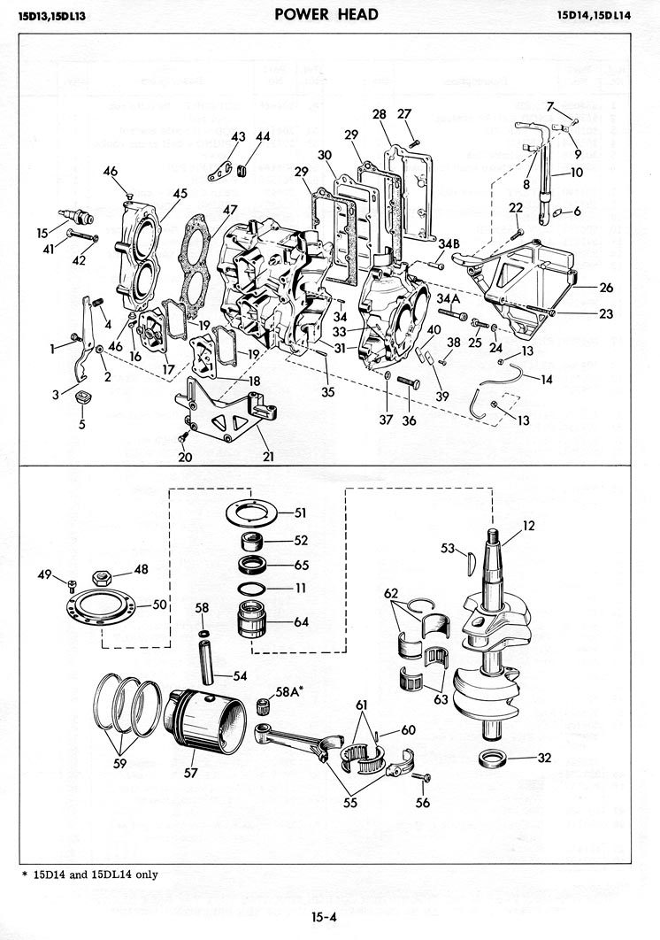
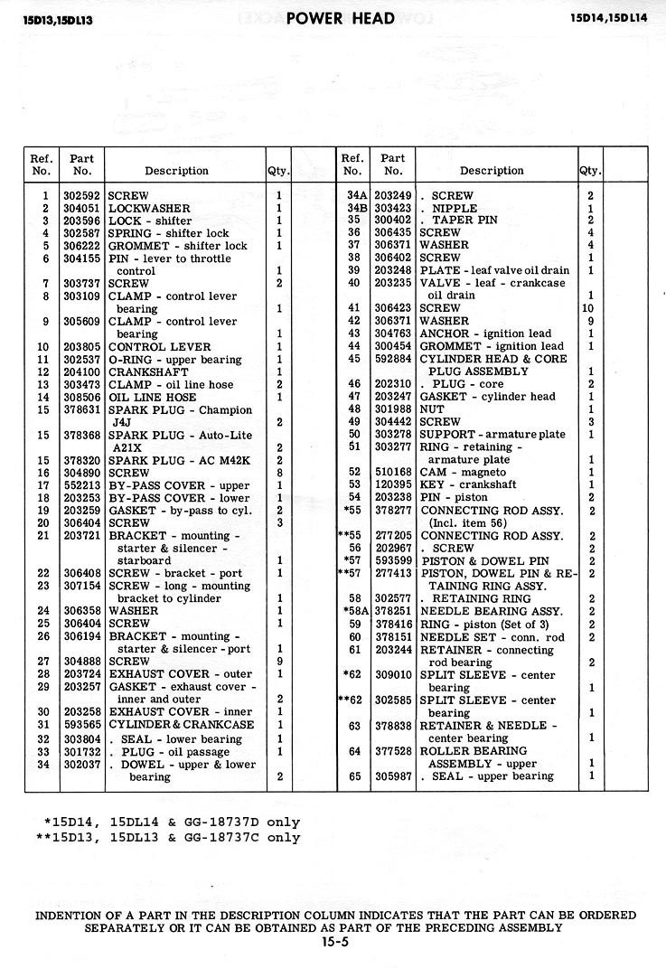
December 30, 2021 at 1:12 pm #251967Did I hear my name mentioned? The 1957 was 18hp, bigger pistons, longer wrist pins, etc. So I don’t know about compatibility with the 15hp. But what you might want to explore is the Gale 15hp versions of 1960’ish vintage. They do have roller bearing wrist pin ends. What else is common would take some research.
December 30, 2021 at 1:26 pm #251968December 30, 2021 at 1:45 pm #251972Frank,
Thank you.December 30, 2021 at 2:32 pm #251973I tried to do a little research, but don’t have access to a 56 FD parts catalog. Seems like the big end rod cage and bearings are the same when comparing the Gale to a 57 FD. The wrist pin retainers are the same also, which leads me to believe the wrist pin diameters might be the same. The57 FD 18hp shows a rod using two small needle bearings on the wrist pin end, while the later model Gales shows the more conventional caged needle set up… Guess I should compare the Gale part numbers to a later model FD.
1962 FDs show the same rods as some of the Gale 15s, so am not sure just what the differences are…December 30, 2021 at 3:33 pm #251984I tried to compare the 56 FD 10 parts list to the Gale list that Frank provided above:
The Gale list shows that the crankshaft numbers differ.
The piston pins on the FD 10 and Gale have the same number, 203238
The con rod big end retainers on the FD 10 and the Gale have the same number 203244
The conn rod assembly on the FD 10 and the Gale have the same number but only for early Gale motors. 277205
Later Gale motors incorporate a needle bearing assembly 378251 on the small end of the con rod.
But that does not say the later rods are interchangeable.
I should just remove the rods/pistons from my motor and see if there is wear between the pistons and the wrist pins.
If there is wear on the pistons/wrist pins I would need to replace the pistons and pins and either replace the rods or bush the existing worn rods.
I need to find out if NOS parts are available. .
Then I need to decide about continuing to try and fix this motor.
December 30, 2021 at 7:25 pm #252002Thank you to Mumbles, Fleetwin and FrankR for the good advice and info above. 🙂
December 30, 2021 at 8:32 pm #252004This will be an interesting project, keep us posted. I’m guessing the crankshaft part numbers are different because your FD10 uses the single lip seal on the lower end and has a bushing instead of the needle bearing and carbon seal used on the later model FD 18hp models. I guess we would have to measure the diameter of a later model FD wrist pin and compare that measurement to your wrist pins in order to continue this experiment. Hopefully you can just replace the bushing/bearings…
1 user thanked author for this post.
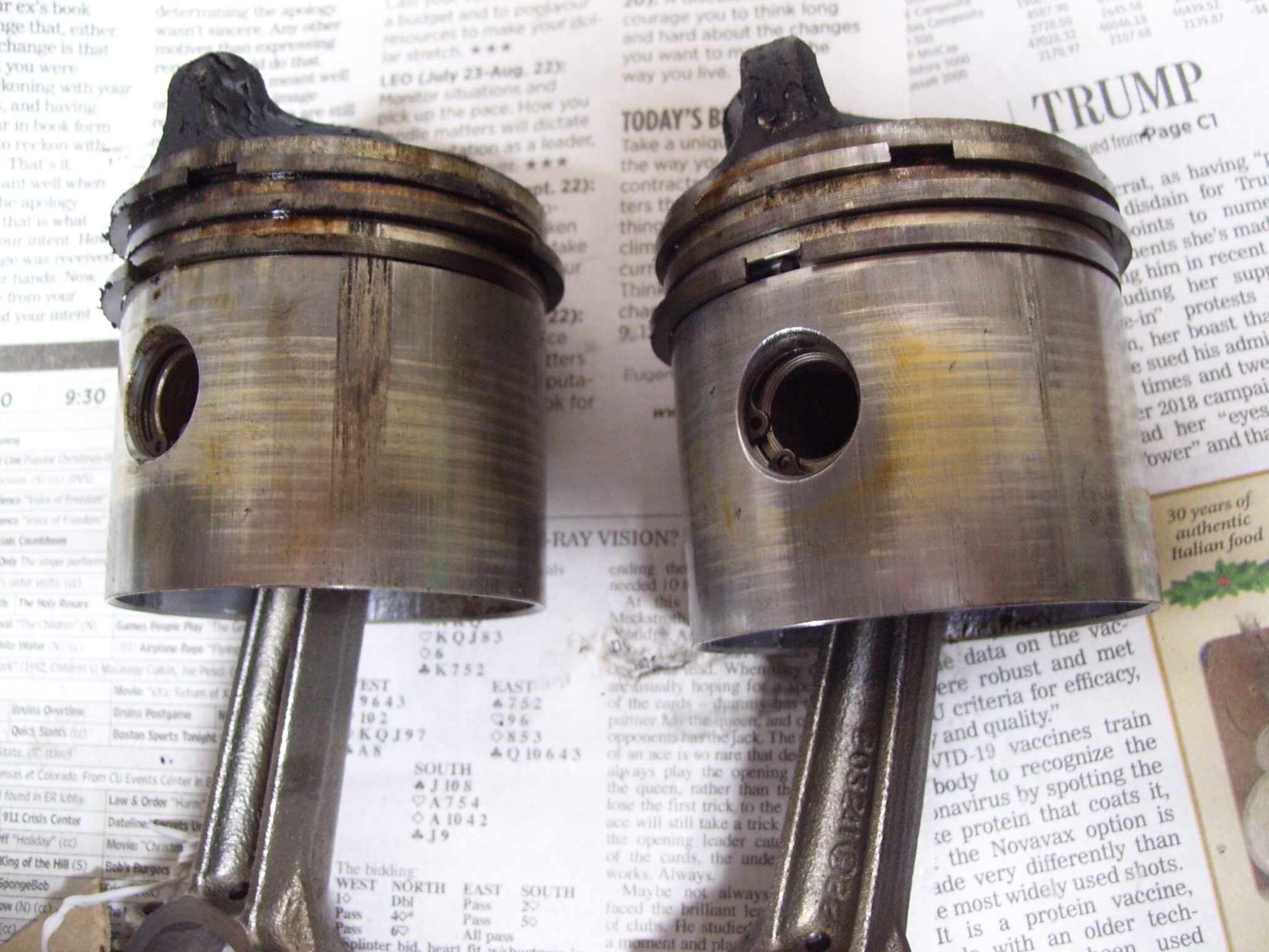
January 3, 2022 at 12:44 pm #252264Took the head off and removed the pistons. The upper piston has wear between the wrist pin and the piston. The lower piston does not appear to have wear between the wrist pin and the piston. Both pistons have wear between the rod small end and the piston pin. (Both pistons are scored opposite the exhaust ports. But I don’t think this scoring is too bad.)
From the parts list for FD-10, I would need:
Piston and connecting rod assembly part 277203 quantity (2)
Piston rings (set of 3 rings) part 301787 quantity (2)Alternately I could use:
Connecting rod assembly part 277205 quantity (2)
Piston and dowel pin assembly part 277402 quantity (2)
Piston pin Part 203238 quantity (2)
Piston rings (set of three rings) part 301787 quantity (2)How do the piston pins (wrist pins) come out? Are they driven from a particular side? Should the piston be supported to prevent bending it?
Thank you, -
AuthorPosts
- You must be logged in to reply to this topic.


