Home › Forum › Ask A Member › 6039 Speeditwin Piston Removal
- This topic has 30 replies, 7 voices, and was last updated 4 years, 3 months ago by
 garry-in-michigan.
-
AuthorPosts
-
December 11, 2019 at 12:36 am #189163
This is beginning to reveal how little experience I have with opposed twins. But one more point, then I’ll shut up. Whichever end the assemblies end up in, make sure any oil holes (if any) in the rods are “up”.. I’ll watch from the sidelines now.
December 11, 2019 at 6:03 am #189171I think that the pins are supposed to have the open side down, maybe to keep from holding fuel?
Just my opinion, and I recall that the Speeditwin/ Speedifours I have worked on were that way also.
No big deal, is just install them correctly after cleaning, etc.Keep the pistons matched with their respective bores.
As for rings, PN200576 is for standard size. If you can find em. I think new ones can be had from the piston ring guy. Make sure you get the ones with the notch for the little pin in the piston groove.
And yes that crank taper and key way look horrible. If it were mine, I’d be on the search for a good replacement. A good crank taper and key is extremely important with these opposed twins.
Mark
December 11, 2019 at 7:53 am #189173Something just occurred to me…this was the motor with the broken prop shaft right?
If so, I submit to you that this worn crank taper is/ was the root of the problem.Loose flywheels on big opposed twins will cause a serious back and forth knock all the way to the shear pin. Especially at idle.
Sadly, i had this happen on a PO-15.
Ruined the crankshaft, flywheel, and sheared the 5/16 shear pin. All in about 10 minutes.I have 4 running 6039s and several leftover parts and pieces, but I have no good crankshafts.
For me ( and I am a machinist) I wouldn’t fool with welding it up and recutting the taper and key.
Also, I would guess that the flywheel bore is pretty rough as well.I’m sure a good crank can be found.
Also something to consider, the crankshafts seem to be fitted to their particular lower bearing/ rotary valve assembly for a good seal.Mark
December 11, 2019 at 9:36 am #189176Thanks for all the replies.
Good point on the “rod oil holes” Frank!
I was told 40 some years ago to always put things back in the same hole
they came out of, so will try to adhere to that advise.This motor most likely won’t be run more than a couple times a year, but
I do want to make it reasonably “solid”. This is the motor that had the
broken prop shaft. I’ve ordered some expensive epoxy to build up the
replacement end of the prop shaft in the seal and prop area, and will
try this same epoxy to fix up the keyway, and crankshaft taper if
needed. I have a replacement flywheel in good shape.
Epoxy is suppose to come today, but not sure I’ll get the garage warm enough….
14 brrrrr low right now 🙁Prepare to be boarded!
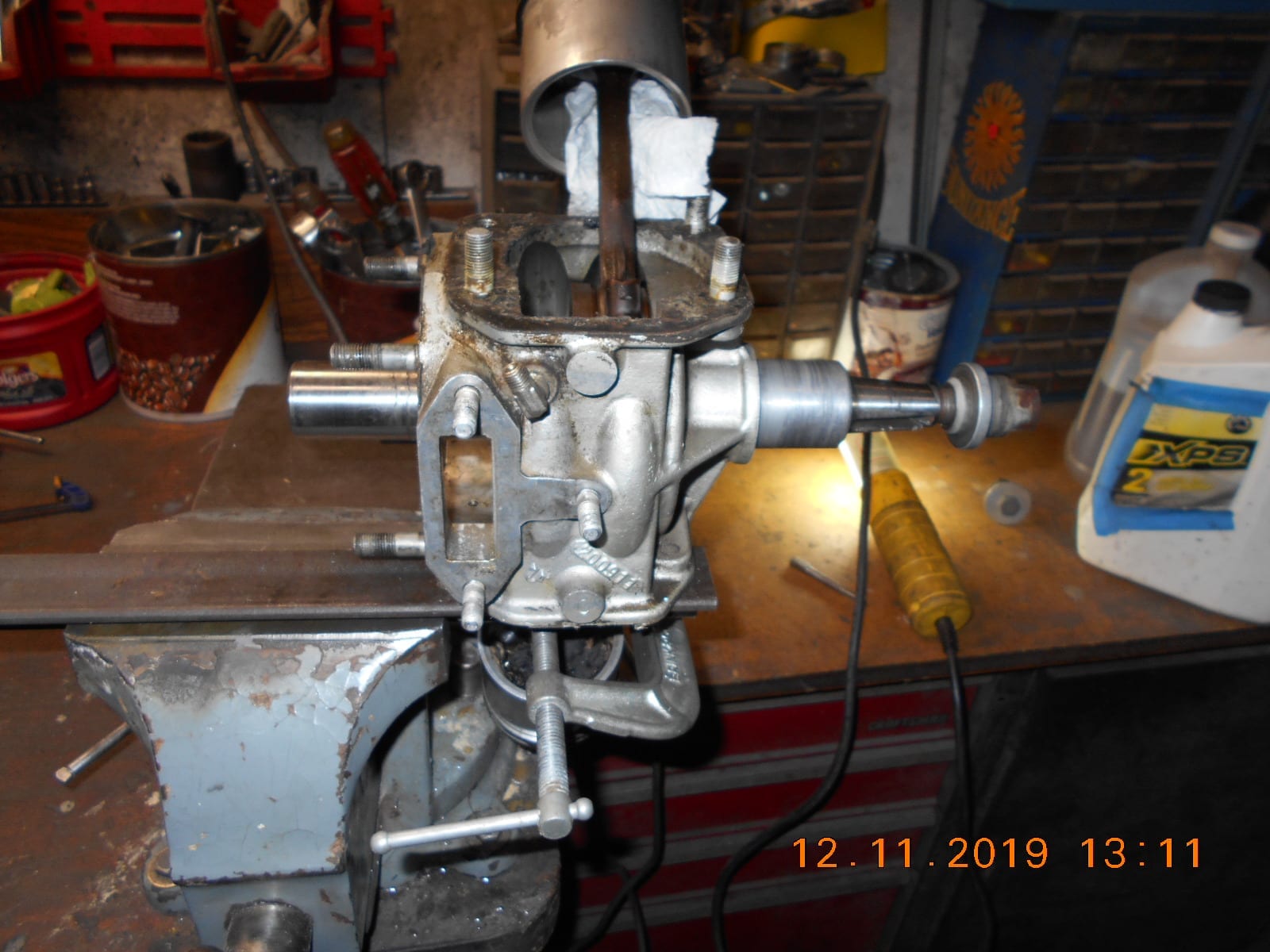
December 11, 2019 at 11:27 am #189189Piddled in the garage on the Speeditwin while trying to get
the wood fire going. I will be able to get at the rod bolts
without removing the pistons. Tried to loosen the rod bolts,
but they didn’t want to budge and it was impossible to hold
the crankcase steady and use two hands on the screwdriver.
Therefore, I drilled a couple of holes in a piece of angle iron
to mount the cylinder in the vise.Frank, Please don’t remain silent just because “opposed twins”
aren’t your forte. I had no idea about the piston pin direction
“hole” pointing down as norm, nor could I find anything in
a Johnson or Evinrude manual to help.
Most importantly perhaps, you mention to check the oil holes
in the rods as “UP”……. mine are “down”. Just hope
the lower unit blew up on the first ride after the power head
was last taken apart!One these opposed twin OMC engines, which cylinder is
designated as #1, Port or Starboard side?
Just thought it would be nice to know in case I find any
old markings on the road caps, etc.
Thanks again.Prepare to be boarded!
December 11, 2019 at 2:41 pm #189192Having worked on many single cylinder motors where the intake ports are on the top of the cylinder and the exhaust is on the bottom, it is pretty much universal that the pins go in with the open end down. Yeah, so they don’t collect a gob of fuel. That’s why they caught my eye. But as for motors where the ports are on the sides, I really can’t say with expertise, or even if it makes a difference.
What is universal, is oil holes are on top of the rods so oil goes in by gravity.
Again, opposed twins are not my field. Salt water had killed most of them around here by the time I started my career. At least killed them dead enough that nobody wanted to pay the bill to rebuild them. But things are different now that they are antiques.
December 11, 2019 at 4:19 pm #189194Since both cylinders fire at the same time I would surmise that they both be the same, #1, but probably just referred to as port cylinder and starboard cylinder
http://www.richardsoutboardtools.com
classicomctools@gmail.comDecember 11, 2019 at 5:17 pm #189195More proof that the left piston is on the wrong side and visa versa. My original post said to use a very long screw driver socket (attachment) next to the piston – then you can use an impact driver to loosen the screws. Swap assemblies with new piston rings. (After deglazing the cylinders) I am sure there is a roll of 2-½” piston rings in the garage at the Cottage. We got them in packages of 100. Unfortunately my sister locked it up when she left and won’t be back for 4 months. We also have a jig to hold them while we cut the notch for the alignment pin.
\ December 11, 2019 at 6:18 pm #189196
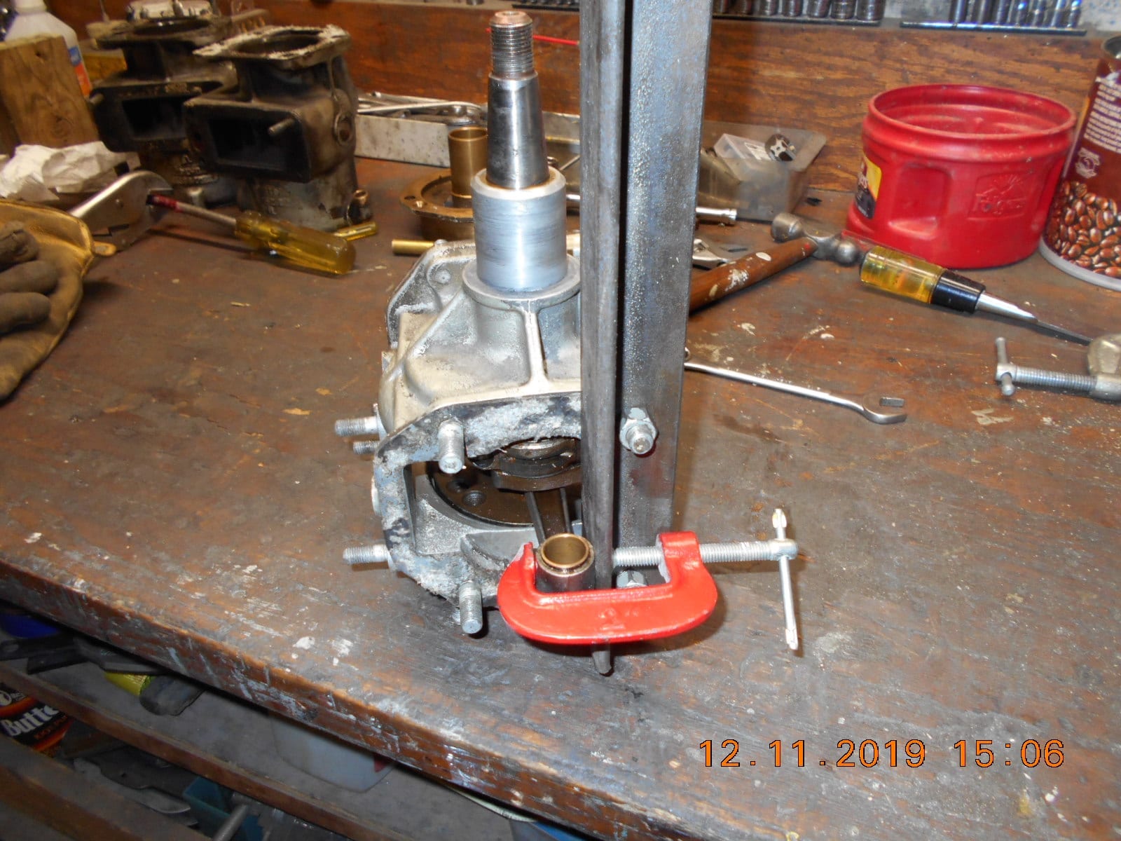
I spent a good part of the day just getting to the point of getting the rod bolts loose.
I had to rig up a piece of angle iron to mount the crankcase in the vise and clamp
the dangling rod / piston to the angle iron so every thing was “steady”.
Got the biggest screwdriver I had and it was impossible to get a good grip
on the rod bolt. Got the torch out and heated the rod around the bolt up.
Took several tries as the screw driver kept slipping. Finally got one loose
and moved on to the 2nd and 3rd with no luck.
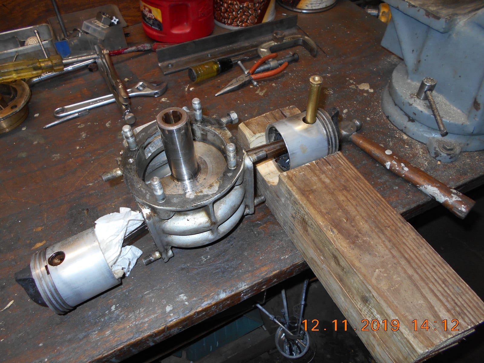
Decided the pistons “had to go”…… got tired of them flopping around and
afraid of breaking them. Spent the next hour making a wood piston anvil.
Not having a 2-3/4” hole saw, radial arm saw, hammer and chisel had to suffice.
Not being sure in which direction to knock the wrist pins out, I taped on the
solid ends, and they came out with relative ease.
Life was much easier with the piston removed.
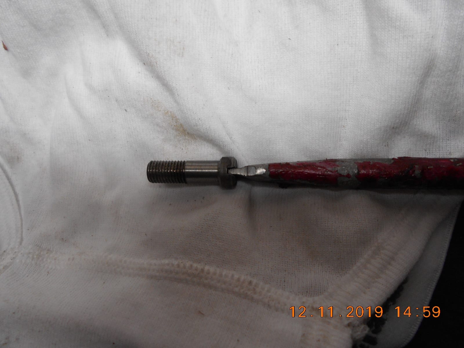
I got the smart idea to remove the one loosed connecting rod bolt and
checked the fit in my screw driver. The screw driver was only going down
in the slot about half way….. no wonder it was slipping. Some custom
fitting of the screw driver on the belt sander soon fixed that.
I still needed to use the torch on each rod bolt, but they are all loose now.
Decided to take a break and let things “cool off” before I tackled removing
the rods, and all those loose roller bearings. Bet they’re going to be fun
getting back together.I mentioned in a prior post that my connecting rod oil holes were pointing
down, not “up” as Frank suggested. Wasn’t quite true. Only one
was pointing down, the other “up”. Turns out both rods are
the same part number, with an offset piston pin boss and with the
oil hole for the wrist pin drilled the same.
Funny thing is, I believe the parts list only shows one part number
for the connecting rod. Can anyone verify that? My list is very
hard to read.Garry, I have not researched the availability of piston rings yet, but pretty
sure I measured the pistons at 2-3/4″, not 2-1/2″, when I made the
wood anvil.More later!
Prepare to be boarded!
December 11, 2019 at 8:26 pm #189203Sorry about my faulty memory – Of course you are right – they are 2-¾” rings. I don’t like to use heat on those. Too much will mess up the heat treating and shorten the life of the bearing. I find a hand held hammer driven impact driver get the job done without the use of heat.
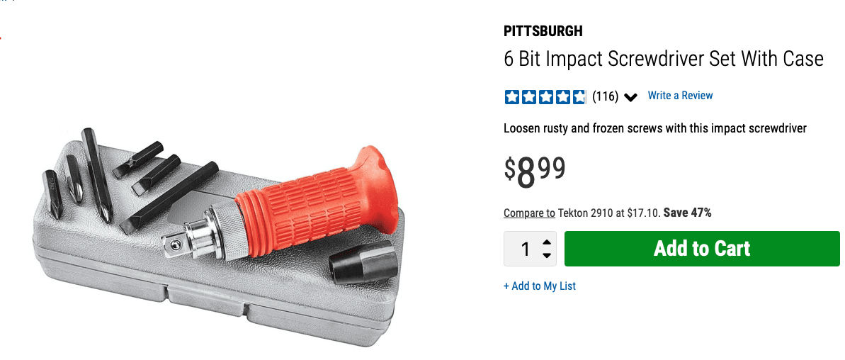
Get a foot of this hexagonal rod and grind one end to fit the screw – then use the impact driver . . .
-
AuthorPosts
- You must be logged in to reply to this topic.