Home › Forum › Ask A Member › Evinrude 4425
- This topic has 13 replies, 5 voices, and was last updated 9 years, 3 months ago by
bakercheese.
-
AuthorPosts
-
December 30, 2015 at 9:14 pm #3296
Who is familiar with this motor ? I have one that won’t pump water. I disassembled it and replaced the 2 impellers that I found on Ebay. Still won’t pump ! I do not understand how water gets thru the pump housing and up to the power head. From the diagrams that were posted on here a couple of weeks ago, I believe it’ s assembled correctly.
Any help out there ?
Ron…bakercheese1949@hotmail.com or 612 5086639
ThanksDecember 30, 2015 at 9:40 pm #29403Have you by chance checked to see if water flows up through the tube? Something above the water pump could be plugged.
December 31, 2015 at 12:29 am #29418What tube? I guess I don’t understand how this works. This is unlike the mid 50’s motors that I’m used to working on. There isn’t an actual tube that attaches to the pump body. Therefore I’m not sure how water gets to the motor
December 31, 2015 at 1:33 am #29422There should be a means of getting the water from the water pump, up to the engine block. Typically, there is a tube of sorts, inside the midsection.
December 31, 2015 at 1:34 am #29423Have you had the gearcase off? If I remember correctly, there’s a small tube in the exhaust housing which has to align with a hole in the gearcase. This tube is cast into the housing and only sticks out a little bit on the bottom. To line it up I use a flashlight and a small screwdriver or something to make sure it’s right. I might be thinking of another motor but I’m pretty sure it was on these Sportsman motors.
December 31, 2015 at 2:26 am #29430Thanks. I’ll take another look
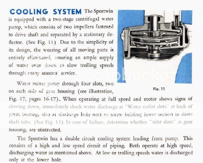
January 4, 2016 at 7:10 pm #29656I found this pic in a 4425 manual showing the water circulation thru the pump. It also shows the tube I mentioned which is on the right hand side. Look carefully at your pump as there are little alignment nibs cast in which must line up on assembly.
 January 4, 2016 at 9:10 pm #29659
I don’t believe a 4425 has a water tube as such. It is a passage cast integrally in the swivel tube and pump housing. I am posting a picture which I am quite aware is NOT your model, but attempting to explain how the water gets to the powerhead. This one does have a short copper tube leading to the cast-in tube (ignore it).
As for your motor, are you running it in a tub? If so, try running it with the propeller removed. Centrifugal pumps balk at working in turbulent water (tubs & barrels). Another thing to check is for a missing welch plug above the pump.
January 4, 2016 at 9:23 pm #29660Yep, that’s what I was saying in my earlier post. I’m inclined to believe that there is a blockage in there somewhere, if water isn’t getting up to the engine and I bet it may be at that elbow.
January 5, 2016 at 1:08 am #29670Several things come to mind.. The pump plate and deflector plate need to be in place as pictured in parts diagram Frank included. On the deflector, there is a stamped fluted center which can have a tendency to get misshapen or even busted or hogged out, its very thin metal… This seals with bottom lip of top impeller. Make sure the plate is present and still spot welded in deflector.Its also important that the impellers be installed with correct side up. The impellers may have the word UP embossed on them if not yet worn off to ensure this. The lips at the center of the impellers should not be torn or worn and should be facing down.. Basically make sure the curve in the vanes match the picture Frank posted. The other thing is the welch plug mentioned previously… There is a cavity that it cover to make a small opening in leg for water to travel up. The welch plug needs to be in place to maintain force. You can remove it to clean the above passage as needed but need to reinstall welch plug.
Here is my interruption of how it works (hope it translates well 😕 ):
Each impeller draws water from the center then throws it (centrifugal force) to the outer edges. The deflector is designed with a plate spot welded to it that has small gaps at the outer edge inside the top plate. The water thrown outwards from the bottom impeller (stage 1) feeds into those passages then into the center of top impeller (stage 2). The top impeller than again draws then throws the water to the outer edges (centrifugal force). The passage behind the welch plug is the path of least resistance and water travels up leg to powerhead. There is a balance of force and flow. Think of what happens when you put your thumb over the opening of a hose. The pressure for stream increases. Leave hose unobstructed and the volume increases but pressure decreases. That is why its important these passages be as they were designed in size and clearance as well as unobstructed. If you take the welch plug out, the center of defector gets misshapen or hogged out, or bottom plate is missing (turns bottom into a huge open hole) you change how the centrifugal forces are at work. If you have an obstruction, water just wont flow. -
AuthorPosts
- You must be logged in to reply to this topic.


