Home › Forum › Ask A Member › Gas / fuel leak help on a 1954 25hp Johnson RD-15
- This topic has 39 replies, 11 voices, and was last updated 3 years, 5 months ago by
crosbyman.
-
AuthorPosts
-
November 15, 2021 at 4:26 pm #249712
actually when I marked & drilled the plate hole location it got flipped off-set from the bypass cover hole. the bypass cover cavity having been filled with JB weld the drilled vacum pulse hole did not line up to the plate hole.
guess you had to the there 🙂
Joining AOMCI has priviledges 🙂
November 28, 2021 at 6:16 pm #250380I am pleased to report again that I have added a fuel pump, and have re-purposed my return air line to the gas tank as a return gas line instead. Here is what I did…
The first decision was how I was going to get the pulse for the fuel pump. There were three options that I became aware of:
1) Convert the air return line for the gas tank into a fuel pump pulse. I didn’t really care for this option, because it was relatively involved. It meant digging into the air intake manifold and blocking a passage, removing parts, etc. This is the only option on some motors, but I had two other options, so this was my last choice. This process is also not easily reversible. You also have to find a place to mount the fuel pump as well.2) Purchase or manufacture a plate to cover one of the bypass covers on the side of the motor. These plates are available to purchase on eBay. They don’t look that hard to make. The fuel pump mounts directly to the plate. I have plenty of aluminum plate sitting in the garage that could easily be converted. This was my second choice.
3) In this YouTube video from “Brandon’s Garage” https://www.youtube.com/watch?v=FlV8zjm4Y-A he suggests finding a later model bypass cover for your motor that has provisions for a fuel pump, but that fits your motor. I went on the hunt for such an option for my Johnson RD-15. Fortunately, I found this thread here https://www.aomci.org/forums/topic/will-this-fuel-pump-work-on-a-1955-johnson-25-hp-rde-17/ that showed exactly just that. All I had to do is find Johnson part 304646. They were quite pricey on eBay, WAY more than the aluminum conversion kit plates on eBay, but, marineengine.com had several in stock, for under $7. I was sold I bought a 304646.
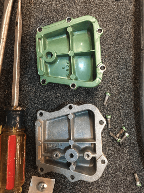
The old bypass cover is shown above, and the new one is shown below, including the hole for the pulses to reach the fuel pump, and the mounting holes.
Next I needed a fuel pump.
As mentioned above in this thread, there were a few options. I was initially excited to find $12 pumps with 5 stars on Amazon, but quickly realized that they were Chinese knock-off pumps. Some people were having issues with them. They said they looked similar from the outside, but were not the same internally as the OEM pumps. I decided it was worth it to get something better.
I really wanted to get one of the smaller, less expensive OEM pumps, but after reading several threads on various forums, the smaller pumps are really only good through 20HP, and can’t handle the demand for a 25hp motor. Especially the older, gas hungry RD-15’s. I decided I should definitely get a pump specifically designed for 25hp or larger. I needed something that fit on the bypass cover, but wanted something relatively recent that would be easy and inexpensive to get replacement parts for.
For 25hp+, Sierra pumps were about $75, and OEM pumps were $90-$115. Yikes! When I found I could purchase a used OEM pump for about $5 on eBay, and a rebuild kit for $18. Perfect. I settled on Johnson pump 438556. I followed the tutorial on Dangar Marine on how to rebuild the pump. https://www.youtube.com/watch?v=bPCHbov4RuY His video was great, and I rebuilt the pump in less than a half hour.
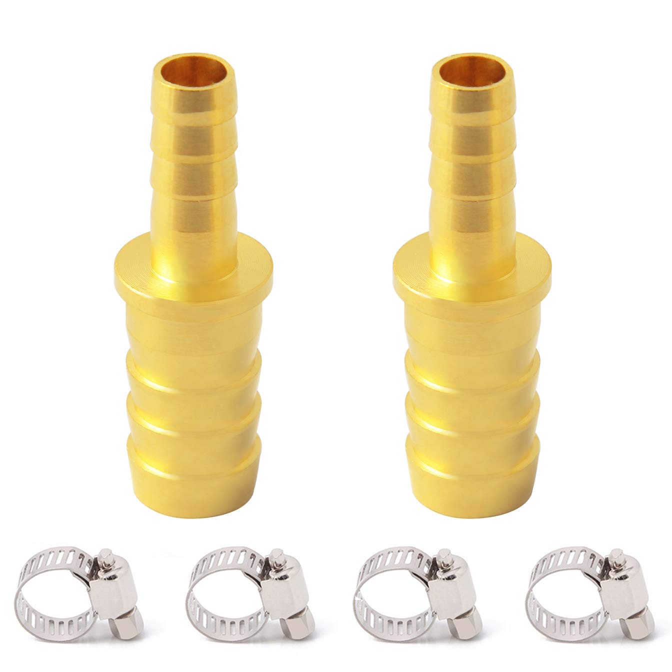
I found that the fuel pump had much larger hose connectors than the rest of the engine. This fuel pump is good for up to 140hp. It has both 5/16 and 3/8 hose connectors on it. I went and bought a foot of 5/16 fuel line at O’reilly Auto Parts, and two hose reducer barb fittings on Amazon. The carburetor and quick-connectors both have 3/16 barbs. I was able to get the 5/16 fuel line on the 3/8 barb on the fuel pump. It was tight, but it fit. Same with fitting the 1/8 fuel line from the nipple on the cover plate to the 3/16 connector on the tank quick connect. The 1/8′” hose will fit on the 3/16″ barb, but it is tight.
A few hose clamps later, and it was all mounted and ready. Before you ask… yes I put hose clamps on the fuel pump. I just didn’t have a better picture of what I did later in the process. It was dark and I had already put the cover back on. Taking the covers off the RD-15 is a huge pain!
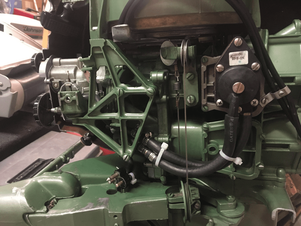
I then unattached the return fuel line from the gas can and started up the engine. It ran great, and gas was flowing out of the return air (now fuel) line as hoped.
I ran it in a barrel for a good 10 minutes to make sure that everything was working properly.
I then took it out to the lake yesterday, and ran it at full throttle for a few miles and it all seemed to work great. No extra gas cans, no oil slick on the water. Just a perfectly functioning motor, top speed and idle seemed unaffected.
I couldn’t be any happier. Thanks again everybody for your encouragement and help.
November 28, 2021 at 6:35 pm #250387So after using this setup, I have two questions for those of you who have operated their pressurized tank with a fuel pump, while using your return air line as a return fuel line.
Do I need to loosen the fuel cap on the tank when I run the motor?
There is no vent on the fuel tank, so I was curious. I tried closing the cap and letting the motor idle for a few minutes, but it didn’t die. I was wondering if perhaps enough air and fuel was coming back in through the return fuel line, that I didn’t need to crack the cap open? I assume that if I run the motor at full throttle, it would probably die…?
Just curious if I should make a habit of unscrewing the gas cap a bit when running the motor or not.
Should I bother worrying about the gas/oil mixture as I get to the bottom of the tank? If so, what do I do about it?
I understand that the return fuel will be a bit rich in oil vs my original mix. The motor calls for 16:1, and I have ready most everywhere that 24:1 is fine. At 24:1, the motor is still smoking while idling out of the marina, so I assume it is getting plenty of oil. If I just never dump the excess oil out, I assume that I will just be running with more oil than 24:1, and that’s fine. Maybe the bottom of the barrel will be 16:1, and when I fill it back up it will go back to 24:1. Close enough? I use an electric motor for trolling, so this motor will typically only be used at higher RPMs, so more oil seems fine to me. Just making sure that my thought process is on track here.
Thanks!
November 28, 2021 at 7:31 pm #250399I would stick to 16-1 and vent the tank. can you add a vent screw.
November 29, 2021 at 8:35 am #250402IMHO & in theory your return to the tank purge line is being pressurized with a mix of fule oil and …air coming from the downstroke of the cylinders used to push out the crankcase residues.
that said if you ran 30 min. on the lake and the cap was closed you have your answer …
the fuel sucked out of the tank de- pressurises the tank (cap closed) and the return line is pressurising it back up and more since the air volume pushed out from from the crankcase cavities is much larger in volume, compared the fuel pumped out out of the tank.
jmho if it works don’T fix it 🙂
btw you should have your excellent work & pictures published in the Outboarder so anyone wishing to save the environment can go ahead in confidence and recycle all that polluting oil/fuel currently
being flushed into the water.your engine is getting close to ETEC standards ! 🙂 Surely better than a 4 cyl with all their crankcase oil not being recycled properly beind the barn. 🙁
Joining AOMCI has priviledges 🙂
November 29, 2021 at 11:20 am #250412Yes; as Crosbyman said….excellent writing and images. Thanks for taking the time to share with the forum here. I’m surprised that marineengine sells those covers so cheap! Must be a mistake LOL…..
November 29, 2021 at 11:44 am #250413Crosbyman, thank you for your response. I believe my current system is working, and I’m happy to leave it as is.
I did forget to mention that I capped the 4psi air supply on the intake manifold with a vacuum cap from O’reilly Auto parts and a hose clamp, as suggested in the book, “Cheap Outboards: The Beginner’s Guide to Making an Old Motor Run Forever”. This seems to be working fine.
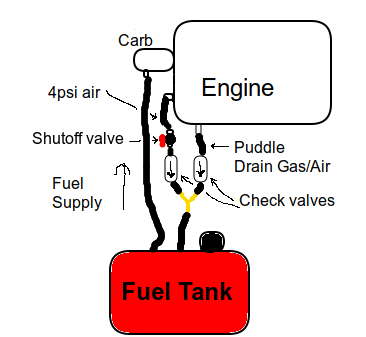
That being said, I had an interesting idea this morning that I would like feedback on. What if, instead of adding a fuel pump to the system and worrying about venting the fuel tank, what if the excess fuel was simply added to the return air line. Something like this:
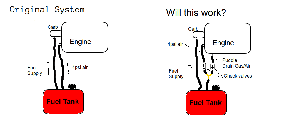
You can get small, fuel rated check valves on Amazon line these:
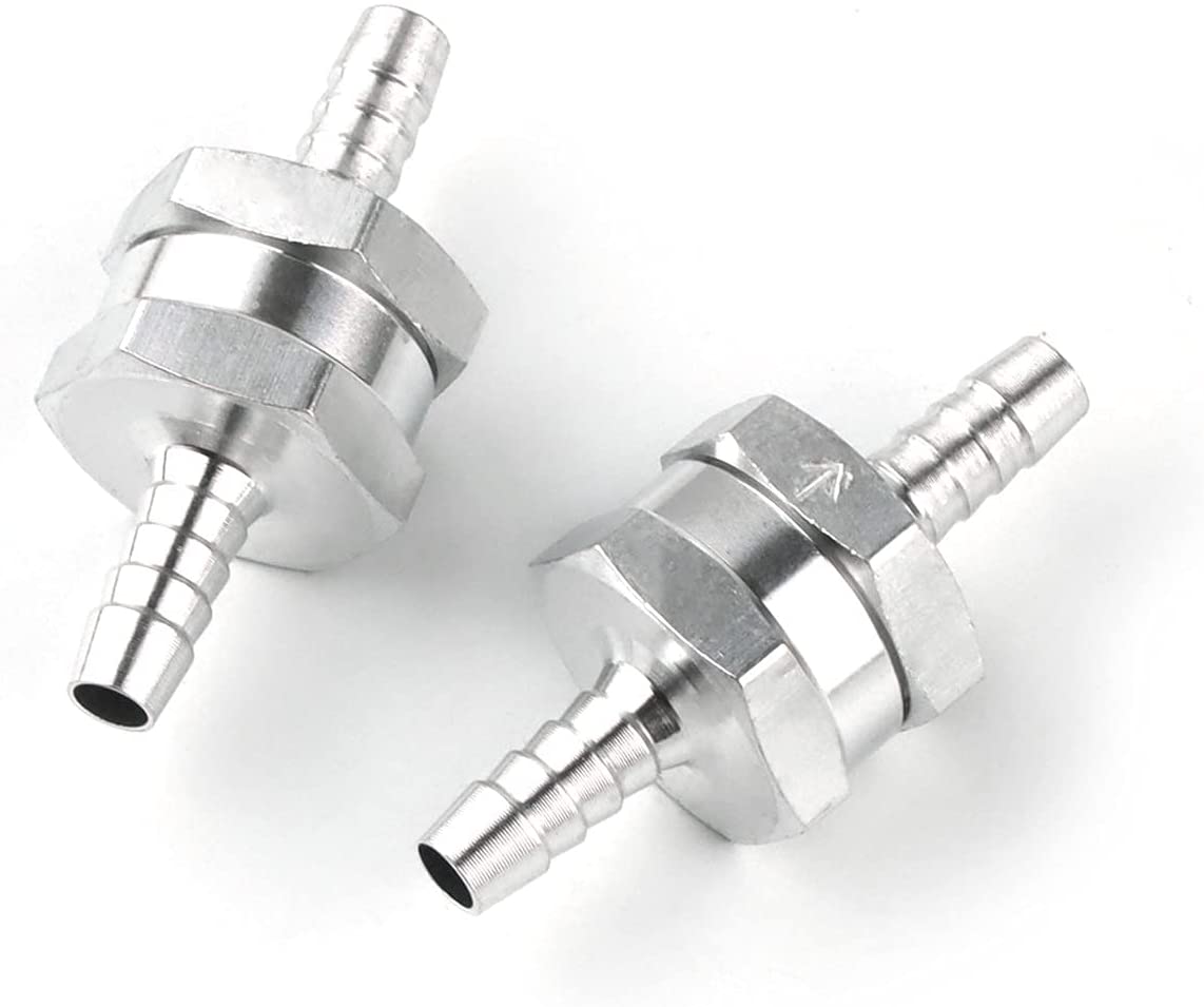
The 4psi air from the engine would be run through a check valve to stop any gas from going back into the air supply, and the puddle drain would also be run through a check valve to stop the 4psi air from stopping the gas from escaping the crankcase. These two check valves would then be joined in a “Y” fitting, that would dump into the air return on the pressurized tank.
There are check valves up stream on both the 4psi air, and the puddle drain, and I believe they are both roughly at the same pressure from the crankcase. I assume here, that they exact pressures of those systems would be the key to making this drain system work, or being a complete failure. The pressure of the puddle drain gas/air mix would have to be greater than the pressure of the 4psi air from the front of the intake manifold, or the 4psi air would close the check valve draining the crank case causing the crank case to fill up with gas/oil mix and not drain. There is a good chance that this would simply not work. I say 4psi, but the manual actually states that the tank pressure system is 4-7psi. If I understand the system correctly, there are two check valves from each cylinder that are used to pressurize a constant flow of air from the engine. Perhaps in order to make such a pressurized tank gas return system work, the 4-7psi line would have to have a much smaller diameter hose installed in order to drop the pressure adequately to ensure the puddle drain check valve could open. The tank itself already has an over-pressue valve on it, such that if too much pressure was built-up from the two air sources, it would be released.
I like that this idea would keep the engine as stock as possible, without a fuel pump, allowing for this engine to continue to be unique and use the original pressurized tank as designed, but would also allow the excess fuel to be recycled into the tank.
As interesting as this all is, my new fuel pump is working great, and I’m tempted not to touch the system since like you said, if it isn’t broken, don’t fix it!
Crosbyman, I don’t think I am necessarily “qualified” or experienced enough to write an article for a magazine on this topic. Outboards are relatively new to me, but I would be fine co-writing an article if you would simply be willing to look over what I write via email, and make sure what I’m saying is correct, and put your name on it as well.
Thanks, and I welcome all comments and feedback on my proposal. Thanks!
November 30, 2021 at 6:36 am #250476Interesting suggestion to say the least . As to the issue of equalizsing the the purge line with the air pressure line I suspect the air pressure would be quite similar coming from the same crankcase cavities on the downstrokes.
why not just give it a try and feedback to us on your findings ….should you choose to “revert back”
One suggestion if you can…. use a clear line between the purge and check valve to see if the purged juices do flow out nicely to the tank via the check valve set up.
I have a nice 5.5 CD I may try this in the winter 2022 projects waiting in th basement ( 2x4hp and one CD 5.5 Johnson) .
Joining AOMCI has priviledges 🙂
November 30, 2021 at 12:55 pm #250494If the pressure from the purge line and the air pressure line are roughly the same, could we not just hook the purge line directly to the tank and call it done? No fuel pump, no extra check valves, y fittings, etc? That would by far be the simplest solution.
The questions left to answer there would be, would the pressure be adequate regardless of RPM, and the amount of fuel being dispensed? I would want to test it at idle, at WOT, when it’s hot outside, when it’s cold, etc, just to make sure it would be reliable.
The next thought I had would be if the purge line did not provide adequate pressure, perhaps could we use a fuel shutoff valve on the air pressure line to control the amount of additional pressure added to a “y fitting”?
I’m talking about adding something like this pictured below, and crack it just enough to make sure there is enough pressure in the tank to push gas into the carburetor, but not so much as to block the check valve from the purge line.
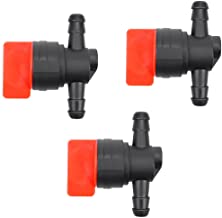
Something like this:
I find all of this very interesting, and I intend to try this, but unfortunately not any time soon. I put my boat away into storage this last weekend, and promised my better half that I would work on other projects for the foreseeable future. After the weather warms up in the Spring and I pull the boat back out, I can report back.
December 1, 2021 at 12:21 am #250516all sorts of options ….good luck let us know how it goes… I would just use check valves and aY connector
Joining AOMCI has priviledges 🙂
-
AuthorPosts
- You must be logged in to reply to this topic.