Home › Forum › Ask A Member › How do Atom Computer Ignition modules work?
- This topic has 215 replies, 30 voices, and was last updated 8 years, 6 months ago by
joesnuffy.
-
AuthorPosts
-
June 15, 2017 at 9:54 pm #59746
I have copy etched a few boards, they were ugly but worked. Next step is to photo etch for a cleaner set.
Ken W
June 16, 2017 at 6:54 am #59764Interested in how you get on Ken with IGBTs. I have enough 2SD1071s to last me the rest of my lifetime about 20 of them. And ive only got 5 outboards & 1 lawnmower to use them on.
June 16, 2017 at 12:00 pm #59771If it was not for DeBe’s foresight, the schematic for the Atom Ignition Modules (Red, Brown, and Blue) would still be a mystery. He help me with many questions five years ago when I first ran across his work. With the stock of Atom’s modules disappearing the need for a reliable solution is needed.
Thanks
KenJune 17, 2017 at 2:00 pm #59827Ken,
The motor looks to be an OMC you put your module into so it has a negative ground. So I am guessing you didn’t have to use the silicone under the BU931 because you just grounded it to the block correct? and the positive side that the coil wire goes to is to leg E on the BU931? I got 4 modules built but they sent the wrong capacitor got to swap them.Thanks,
JoeJune 18, 2017 at 1:37 pm #59871I found the the collector tab on the 931 can be placed to ground on the OMC and WICO mags, giving it a great way to transfer the heat away. This gave me only one connection point. I do not have any Mercury’s to try this module on at time.
Ken
June 18, 2017 at 1:51 pm #59873Thanks for the info. I do have a mercury distributor on my work bench. I can put a module in one when I get mine built. It is for a 4 cylinder 2 stroke but it does have the rotor button so it to choose the cylinder that gets fire by using the distributor cap.
Joe
June 19, 2017 at 12:50 am #59912I built my first working modules today with success.
I am in no way a electronics guru but I do have good soldering skills.
I will post the diagram no mosorb diode was used but I did use a .2 uf panansonic orange drop capacitor. available at digikey I will post part# P12106-ND (.2UF 5% 400vdc RADIAL)
Folks here use the orange drop capacitor to replace condensers and they give me outstanding results using my stevens 75 meter. Escpecially the leakage test they pass it instantly where a good OMC condenser takes 1 to 2 seconds to pass. I am hoping that will help keep my module alive.
The only difference in the module wiring diagram I am posting is I used a .2uf Orange drop capacitor from digikey not the .47uf capacitor.
I was using a BD649 transistor. After contacting Debe he told me they don’t hold up but I had 10 on hand because I had looked at wrong diagram posted in that thread to use them. I have since ordered the correct transistor the 2SD1071 which I will be using next but I thought I would give them a whirl since I had them.
As luck would have it I ordered the wrong capacitor for the build I ordered a .0056uf 50Volt Ceramic capacitor. The correct capacitor was suppose to be a .47uf again I am not a electronics guru.
The .0056uf capacitor was giving me spark I paired 3 together and they did also. I decided to do something after measuring the 3 paired .0056 uf capacitors with my Stevens 75 tester and they barely brought the needle up. I decided to try a Orange Drop Panasonic .2 uf capacitors basically thats is under half the value of .47uf It also worked and I got good fire on plugs. I thought well one thing I have learned here is that the capacitor is married to the type coil used. What I mean by that is that when people put a OMC coil on a Scott Atwater or a outboard it wasn’t suppose to go on folks use the condenser value that goes with the coil used. Just a fluke I would even try this since I ordered wrong capacitor. The 1952 3HP Johnson motor wound up like it should to WOT so the timing and hi-end rpms was not hindered.
I ran the engine for like 1.5 hours today. It was my uncles he purchased it New in 1952 he’d be 105 years old he died at 97 and I am sure he smiling in heaven right now he used it for duck hunting in Maryland along with his brother. It is my favorite motor.
It had the original coils and plug wires. I started engine and it ran fine for like 30 minutes then a cylinder dropped off like one stopped firing except with higher rpms. I changed the plug wires with new ones and that problem went away but module didn’t die which was my hopes. I am testing these and thought would use old plug wires and old coils to try and kill a module but they didn’t. I know the nova ii dies easily when using old omc coils and I suspect that’s why so I am in the testing mode not a finished deal by any means.
I ran it some more with good results with new plug wires and original coils and old spark plugs who knows how old they are but the plugs cleaned up nicely after running 1.5 hours (in a barrel) burning clean and dry. The motor runs smoother than I have ever got it to and slower I can move the speed knob past what I used to get for low speed. I have owned it like 25 years and can turn idle way down now past what it use to since I had it marked with sharpie. I can’t wait to try it on a boat 2 morrow.
The mosorb diode was not used on this test I have several on order. I am using the orange drop .2uf panasonic capacitor not a .47uf everything else is the same and hoping the BD649 doesn’t die. I will run it 2 morrow weather dependent wot for at least 2 hours and slow her down and idle speed for 2 hours for a combined 4 hours run time.
Thanks to all,
Joe
June 19, 2017 at 11:01 pm #59972The weather wasn’t the best today but got about an hour of run time on the lake. This 1952 3hp Johnson twin motor is always in gear which makes it a good candidate for my tests.
Wide open to long slow troll speeds on a aluminum 14ft Starcraft 1965 boat allowed me to really dial in carb. The low speed needle was almost on the money the high end needle had to be ritchened slighlty not much compared to in the barrel tuning. Both needles had to be leaned a lot even in the barrel after the atom ignition was installed leading me to believe the motor is way more efficient. Also to be noted: I am using the original coils with new ignition wires.
I don’t think this motor has ever ran this well even New. From slow troll speed which was way lower than I have ever achieved with this motor/points and condensers to high rpms going back and forth with long slow speed idle runs she went to high speed quickly and no hesitation. Hoping to post videos soon.
I did pull the old champion plugs which were in motor for a long time and put a new set of NGKs in her this morning which allowed me to lean both needles a tad more in barrel.
In comparison to running her for a couple summers on our inflatable dingy with points and old champion plugs with the addition of electronic modules I dialed both the slow speed adjustment and high speed adjustment back significantly even in the barrel with old champion plugs. I run a racing synthetic oil. I couldn’t even smell the oil burning today almost made me think it was a 4 stroke. I wouldn’t doubt the engine has ever ran this well in its life.
I would like to thank Debe for his hard work and efforts.
I am currently working on a finished, tested, dependable module that I like an with minimal cost and dependability and ease of building which I will share.
Joe
June 19, 2017 at 11:40 pm #59974Thanks for the update Joe. Almost gives me confidence to try to make some myself, once I get some practice soldering.
I wonder if there’d be a market for diy kits among members. I know I would purchase some.
June 20, 2017 at 12:19 am #59977I will share everything I come up with and where I am purchasing parts and which ones etc. I will also post pics of how to I build mine and video of running motor.
I think 2 modules can be built one for negative ground engines and one for positive ground engines which would make building them easier depending on the engine you use it on. I am still learning and testing.
The BD649 transistor I just built some with has to be insulated from engine ground to work on OMC Ken is saying the BU931 transistor doesn’t which means you would just ground it to the block.
Anything is possible so I think that insulating them is most likely the best way so they can be used on either/or type of engines by just reversing the wires. If it won’t spark reverse wires thats simple also.
After looking at Debes Pics of a Red Atom that was taken apart I didn’t see a heat sink only like a plastic case that folds around the electronics like a envelope.It looks like it is surrounded with plastic only no heat shield.
The test modules I just built I suspended the modules in mid air under flywheel using the a ground wire to coil to hold them in place . No heat sink is being used. I think if you attach transistor directly to the motor it might give it too much heat and kill the transistor early just my thoughts. With one insulated from the engine heat it might last longer just my humble opinion and I am testing my theory. A person could also screw a copper penny to the back of transistor if it isn’t touching motor to help pull heat from it.
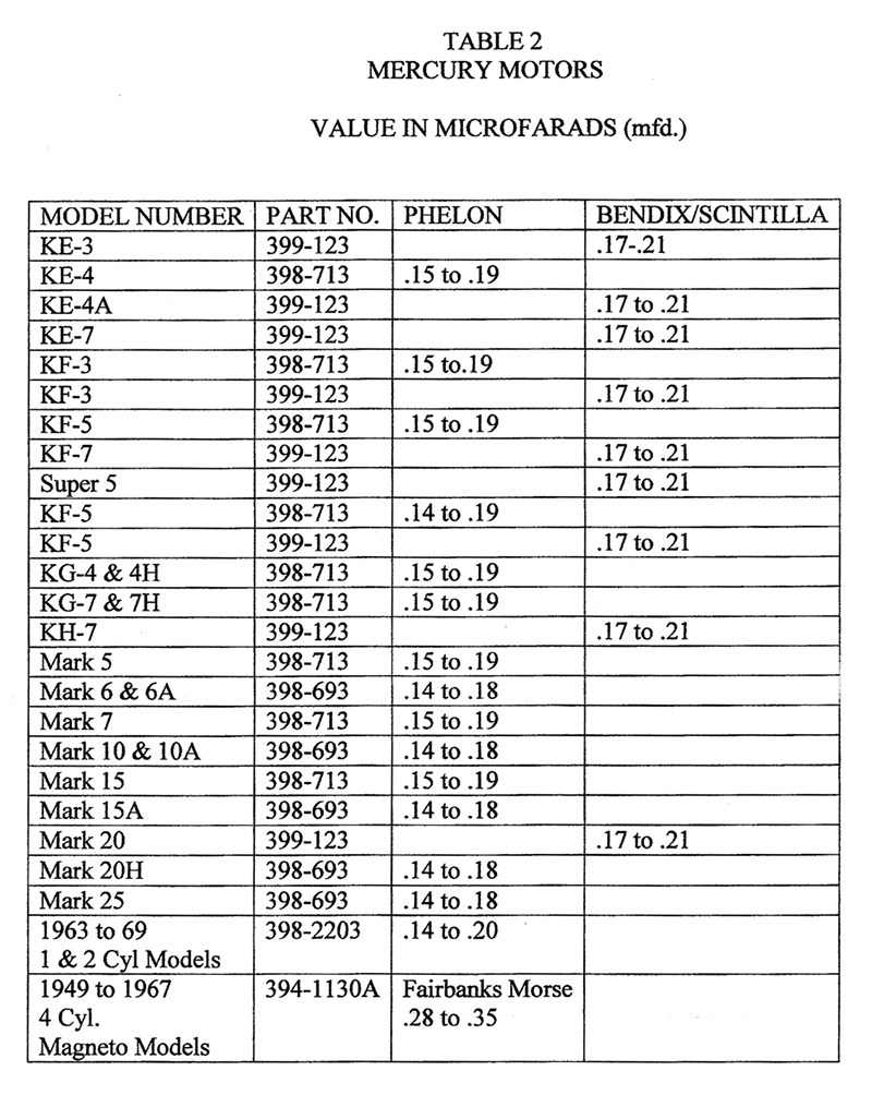
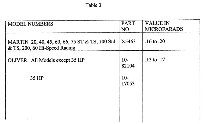
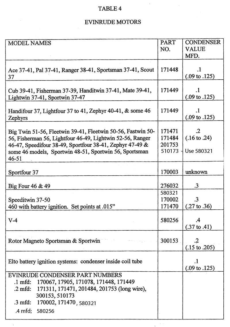
I also wonder if building the module with the appropriate capacitor/condeser value in uf / mfd for the type coil in motor would help keep them alive or more responsive?? Might be nothing might be something. I think condenser values are related to the OEM coil used as these charts show. I will post the charts but different values are used for different coils. I used a similar value good quality capacitor in my build for my module I am using on my type engine coil. I think the .47uf might be a generic value which will work on most coils but might be a tad high for outboards just my humble opinion.
Hope that helps,
Joe -
AuthorPosts
- You must be logged in to reply to this topic.


