Home › Forum › Ask A Member › How do Atom Computer Ignition modules work?
- This topic has 215 replies, 30 voices, and was last updated 8 years, 6 months ago by
joesnuffy.
-
AuthorPosts
-
May 29, 2015 at 1:52 am #17122
The reason the transistor is running hot is using a Sine wave to drive the circuit ( You will destroy an automotive electronic module using a sine wave to drive it. Have done that.) An ignition circuit is a short pulse. Its beter to do what Ken has done to test the module. You could use pretty mutch any small engine that uses points to test it. I use an old Seagull out board motor with out the barrel & piston to test modules. Its just clamped in a vice on the work bench. In debe5 photobucket thers 2 short videos of module testing using a Seagull Wipac & a Villiers ignition system as a test unit.
May 29, 2015 at 6:55 pm #17146I guess I’m having a little trouble with that statement. The modules, when installed and operated as intended, are being powered by an alternator – and alternators produce sines.
You cannot produce pulsed or DC waveforms from a rotary machine, without employing rectification or commutation.
So it’s more to do with the duty cycle of the sine, if you can term it that..? With these simple alternators the slope of the current is very shallow for much of a cycle.
May 29, 2015 at 9:42 pm #17158I have pictures of the CRO wave forms across the primary of an ign coil with no points, when cranked its definitely not a real sine wave. In the particular one tested its a very steep positive pulse & a very small negative pulse. When the module is triggered its a very sharp positive pulse. Using a mains sine wave through a transformer you are not replicating an ignition coil, this is why your transistor is running hot.
May 30, 2015 at 12:33 am #17165quote debe:I have pictures of the CRO wave forms across the primary of an ign coil with no points, when cranked its definitely not a real sine wave.I would definitely like to see those.. can I trouble you to send them? Please check your PM box for an incoming message with my email address.
And yes, it would certainly be better to test it in a closer to real-world application – but as it sits, I don’t have a testbed for the module, other than what I’ve described so far. And after throwing my back yesterday, I’m not up for much beyond swapping wires or twisting knobs at this moment.. what a load of grief! 🙁
May 30, 2015 at 3:13 am #17173The magnetic circuit of a magneto is designed to produce a waveform similar to that which debe describes. A rapid flux reversal occurs over just a few degrees of revolution, producing a narrow pulse of voltage and current in the coil primary. A good description of this behavior, with example waveforms, can be found in US patent 1279750, assigned to the Quick Action Ignition Company (and later bought by Johnson). Magnetos are not intended to produce smooth sine waves, like a dynamo, but rather short energetic bursts.
Patents 2101392 (Wico) and 2472313 (Phelon) are also helpful, although reading patents can be tedious.
John Van
May 30, 2015 at 3:17 am #17174Anonymous
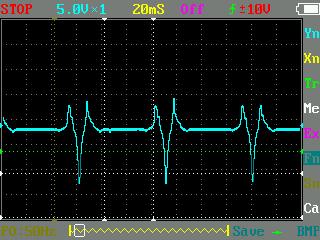
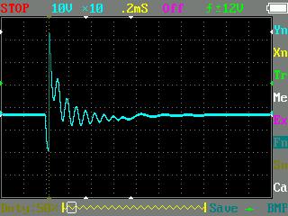
Here are two traces I took a while back with my INCREDIBLY cheap DSO (Digital Storage Oscilloscope) — a toy:
I’m not sure the scale information can be trusted, nor do I have saved information about the hookup (except that I was driving an OMC "universal" magneto on a 3HP block (thanks to Don (aka Fleetwin)) with a variable speed hand drill):
Here’s primary output of the bare coil:

And another with points, condenser, and a spark plug:
 May 30, 2015 at 3:38 am #17175
Have just loaded CRO wave form of a Seagull Wipac coil & module on debe5 photo bucket.
May 30, 2015 at 3:43 am #17176Anonymous
A later patent by the "atom" inventors, US 5,111,798 has a number of plots as well:
https://www.google.com.ar/patents/US5111798And here’s some info about the ATOM inventors:
http://www.kythera-family.net/download/2014%20KAA%20February%20Newsletter.pdfAnd this one of them with an ATOM module & packaging:
http://www.kythera-family.net/index.php?nav=117-121&cid=193&did=7074&pageflip=6With drills:
http://www.kythera-family.net/index.php?nav=117-121&cid=193&did=7071&pageflip=6May 30, 2015 at 2:07 pm #17193Thanks Phil for the information on Atom Industries and the Notaras brothers. Very interesting.
It is evident from Phil’s upper scope plot why points timing is important. The optimal time for the points to open is at the top of the large peak. The large peak is where the most energy will be stored in the coil. Opening the points at this moment results in the hottest spark.
May 30, 2015 at 10:20 pm #17228quote jnjvan:It is evident from Phil’s upper scope plot why points timing is important. The optimal time for the points to open is at the top of the large peak. The large peak is where the most energy will be stored in the coil. Opening the points at this moment results in the hottest spark.Assuming that’s a current waveform, then yes, you want to fire at the highest peak – which represents the greatest dB/dT. If it’s voltage, well.. then current could be lagged up to 90′.
Still the same.. what are the chances that current peak coincides with the correct crankshaft timing angle? 😀
-
AuthorPosts
- You must be logged in to reply to this topic.

