Home › Forum › Ask A Member › How Important is OMC Ignition Timing?
- This topic has 87 replies, 22 voices, and was last updated 10 years, 4 months ago by
 RICHARD A. WHITE.
-
AuthorPosts
-
May 14, 2015 at 12:27 am #15890
OK, I bought the timing tool from Frank and tried it out. Very quickly, I realized that with my $10.00 analog multimeter, I needed to disconnect the points and the condenser from the connection post. I had the multimeter on the one OHM setting.
While adjusting the points, just as the points opened, the meter needle jumped and that is where I left the adjustment. I turned the timing fixture 180 Degrees, and adjusted the second set in the same manner.
I checked the results out with timing light, and it looked to be better than the pre-adjustment check.
The results were a motor that runs and idles better than before, so for me this was worth it. I have become a believer, and from now on I’ll use the fixture instead of a feeler gauge.
Improvise-Adapt-Overcome
May 18, 2015 at 12:53 pm #16317quote legendre:This is the issue, and it’s why you can’t use a light or buzz-box – neither can really tell the difference between 0 and 1 ohms….If you’re using a continuity light or buzz-box, there’s no discernible difference between 0 and 1 (zero and one) ohms – either state will illuminate the lamp or buzz the box.
Nonsense. Buzz boxes are used to set airplane magnetos so you can be assured it’ll work just fine on an outboard. The buzz box won’t make any noise until the moment the points open. I’ll try to upload a video to YouTube to illustrate my point.
Here is a short video I just made. Sorry its not that good. It was tough to film by myself.
https://www.youtube.com/watch?v=rqZWiFIVI5g
Wayne
Upper Canada Chapteruccaomci.com
May 18, 2015 at 12:57 pm #16318quote Richard A. White:quote wbeaton:I set up hundreds of motors without the timing tool and they all worked just fine. Then one day I tried a timing tool and I Was sold. It was faster and provided a perfect spark. I would never went back to the feeler gauge. I use a buzz box instead of a multimeter. It works much better and you don’t have to remove the wires to the points.I obviously fail because every time with wires connected, I get continuity. So please explain with pictures preferably exactly WHERE you place the black and red probes. I can get it to work but I have had to remove ALL wires from the points to get it. Pictures even on just one set of points will do.
Thanks
Richard
Richard, I have always had to disconnect the coil wire to use a multimeter. This is part of the reason I believe the buzz box is superior.
Wayne
Upper Canada Chapteruccaomci.com
May 18, 2015 at 1:39 pm #16322Reading through all this, may I add one thing? The purpose of using the timing fixture is it is more accurate, that is the points will open at exactly the right moment. It also takes the human error out of the feeler gauge method. Besides all that it just plain is easier. Having said all that, once you set the points with the timing fixture, if you then check them with a feeler gauge, they may or may not be exactly .020". If they are not, do not reset them per feeler gauge or you will be defeating the whole purpose of using the timing fixture. In other words, the timing fixture is correct over the feeler gauge.
May 18, 2015 at 3:03 pm #16346All,
I am now so much more confident in this procedure, now that I understand what is doing what..This is why I will not stop paying my dues…This info is too valuable to lose…Thanks to all for a great online tech session. I am adapting the same exact principle to Mercury mags…Regards
Richard
http://www.richardsoutboardtools.com
classicomctools@gmail.comMay 18, 2015 at 3:51 pm #16352quote Richard A. White:I obviously fail because every time with wires connected, I get continuity. So please explain with pictures preferably exactly WHERE you place the black and red probes.Richard
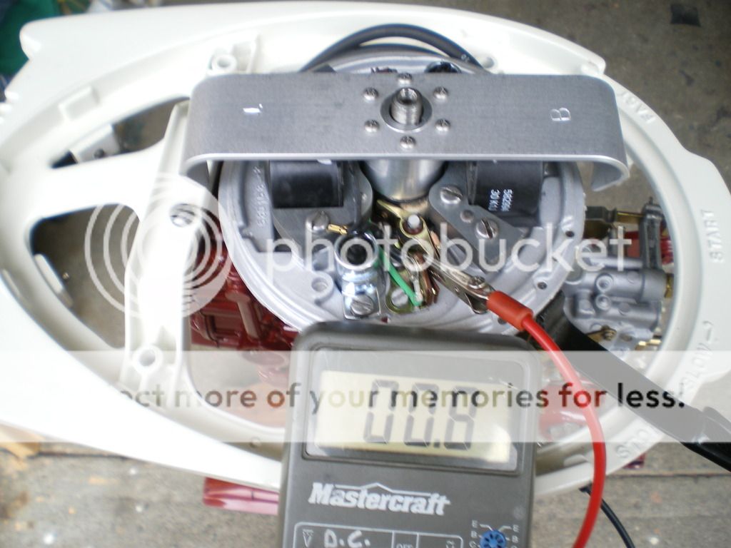
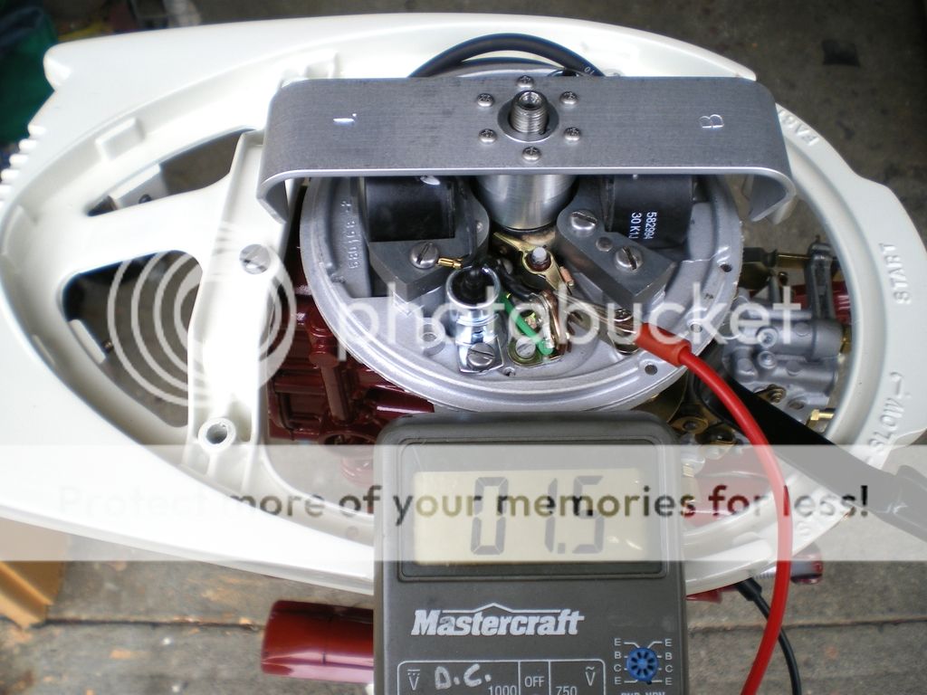
I use a set of leads with alligator clips on them to set up the timing. One lead is clipped to ground while the other one is clipped to the small screw holding the wires onto the points. The reading in the first pic is with the points closed and the test circuit going thru the points to ground. The reading in the second pic is with the points just opening and the circuit being thru the primary winding of the coil to ground hence the higher reading. Doing it this way is very simple and there is no chance of altering the timing while putting pressure on the screw while tightening it up.

 May 18, 2015 at 5:03 pm #16358
The instructions with the timing fixture plainly state that some ohm meters can tell the difference between about an ohm and zero ohms, while other meters cannot tell the difference. At least I thought that was made clear. I’ll have to review what they say.
May 18, 2015 at 6:18 pm #16361quote wbeaton:quote legendre:This is the issue, and it’s why you can’t use a light or buzz-box – neither can really tell the difference between 0 and 1 ohms….If you’re using a continuity light or buzz-box, there’s no discernible difference between 0 and 1 (zero and one) ohms – either state will illuminate the lamp or buzz the box.
Nonsense. Buzz boxes are used to set airplane magnetos so you can be assured it’ll work just fine on an outboard. The buzz box won’t make any noise until the moment the points open.
Totally different situation. Compare the wiring diagram for one of these OMC magnetos to that of your aircraft magneto, and you’ll quickly realize the difference. Also, look at the pics in Mumbles’ post, just above mine – the difference between open & closed points is only 0.7 ohms!
Your typical continuity tester will regard anything below a few ohms as a closed-circuit. One example, the continuity ‘beep’ on one of my meters has a 100 ohm threshold, IIRC. That would never work for one of these OMC mags.. it would just beep continuously. See the issue?
May 18, 2015 at 6:55 pm #16367I’m not interested in arguing with you, legendre. My video clearly shows a buzz box setting the points without issue, which you state is impossible. That’s all I’ve got to say on this subject.
Wayne
Upper Canada Chapteruccaomci.com
May 18, 2015 at 9:30 pm #16377My experience is similar to what Mumbles is seeing.
Measured with all of the ignition wiring intact I’m getting .6 ohm with the points closed and 1.4 ohm with them open. The .6 is likely wiring resistance in the meter leads.
There is a very clear change in readings when the points open.
I’m using a fairly inexpensive Radio Shack digital VOM. (volt, ohm, milliamp)
-
AuthorPosts
- You must be logged in to reply to this topic.

