Home › Forum › Ask A Member › If I have a wiring error, I simply can’t find it…UPDATE: FIXED!
- This topic has 53 replies, 11 voices, and was last updated 7 years ago by
fleetwin.
-
AuthorPosts
-
February 12, 2018 at 1:58 am #9202
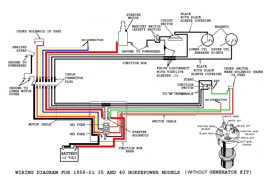
This is the wiring diagram for my engine, except I don’t have a generator or regulator.
I’ve wired & re-wired this 2x now (new wires, new harness, new everything). Everything works great, and I have a perfect spark on each cylinder. Electric start is flawless. Electric choke pulls in nicely.
But I have one problem I simply cannot figure: the ignition kill switch ties the points together, thereby connecting both to ground (inasmuch as one point is grounded at any given moment), and my DMM shows me that all wiring is correct. Except, when "kill" is engaged, only the bottom cylinder goes dark. The top cylinder continues to spark. Every wire is landed correctly on the vacuum switch.
Not to brag (not my purpose or point)…but I’m an EE with a strong background in practical wiring. I understand this wiring diagram completely, and I’ve checked everything over & over. When the "kill" is engaged, my meter says the points are grounded….yet when I crank the engine, I have a bright blue spark on the top.
What am I missing? Any ideas?
 February 12, 2018 at 2:22 am #70907
You are an EE and you are asking us? Sorry, I couldn’t help myself. All in fun, no disrespect intended.
The kill switch, when turned "off", connects the two black wires that lead to the points together. When those two black wires are connected together it will lose spark on both cylinders. You could strip out all the other wires and that would still be so. If it is wired correctly and wires are all intact it will work.
They made many thousands of them that way. So I don’t know what else to say.
February 12, 2018 at 2:26 am #70908BTW, the kill circuit does not rely on the points making ground when closed. Even if they do not ground, the lead is still grounded through the primary winding of the coil.
February 12, 2018 at 2:43 am #70910Furthermore, before you waste time thinking about it, the kill circuit does not rely on the armature plate being grounded. Conveniently starting at the armature plate, the circuit is plate to coil #1 ground wire, through primary winding, to black kill wire, to kill switch, through closed kill switch, to other black wire back to coil #2 primary winding, to coil ground, returning to armature plate, making a complete circuit.
February 12, 2018 at 2:56 am #70911You are speaking of a lanyard kill switch, right? Are you using the right kind, one that closes when the lanyard is pulled? Most are universal these days, but I’m sure you can figure that out.
February 12, 2018 at 3:28 am #70916Not a lanyard, but the same idea…..It’s the kill (shorting) contacts on the ignition switch, per the schematic above.
I am completely stumped. The points are shorted together (confirmed with my DMM at 0.6 ohms), and yet the top cylinder continues to spark when cranking.
February 12, 2018 at 5:53 am #70917How are you cranking the motor over if the key is turned off, killing the ignition system?
Attachments:
 February 12, 2018 at 11:03 am #70919
Both shorting wires go ultimately to the live side of the points. If one set of points is open, then it would seem to me that the entire circuit would be open, even when the key is in the closed, off position. Maybe what the problem is, is that one or both sets of points are considerably out of adjustment, so that when one set opens to make spark, the other side, which should be closed, is actually still open, leaving the whole circuit open. If not totally misadjusted, then maybe the mag plate has so much slop on the center bushing that is effectively causing the same problem of misadjustment.
A lot of the older, smaller Mercurys had a stop button with a third, grounding terminal in them. If you tried to use a regular switch, they wouldn’t shut off. I always felt like that was because the whole dwell strategy on their magnetos was such that there wasn’t sufficient overlap of one set of points being grounded when one was open. Nobody ever told me that; I just assumed it….God help me if I am wrong on this forum….
Long live American manufacturing!
February 12, 2018 at 12:03 pm #70922OK, let’s put on the thinking cap and imagine some unlikely scenario. Suppose kill switch is open and coil #1 is firing normally. Now we close the kill switch, which connects coil #1 and points #1 to ground through coil #2 and points #2, in parallel . That shorts out #1 and it quits firing.
Now, suppose points #2 are not closed as Bill suggests. The kill switch is still connecting #1 to ground via the primary winding of coil #2, and #1 should stop firing. What if the the primary winding of coil #2 has an unusually high resistance? Normal is around an Ohm or less. I have seen reports of some aftermarket coils having higher than "normal" resistance readings. Would that higher resistance be enough to fail to sufficiently ground out #1?
I do not have the answer to that one.But still—even if coil #2 has that imagined high resistance, the #2 points should still be shorting to ground when closed.
Something for an EE to ponder on.
February 12, 2018 at 12:26 pm #70923Timing is set with a timing tool & a DMM…..they’re both about as close to correct as I can get them.
Cranking over: Right now the motor is on a stand, not the boat. The switches (momentary start, maintained choke, maintained kill) are separate individual switches, mounted on a plate on my engine stand, so I can simulate the keyswitch. Still just trying to get things right; not ready to mount the engine on the boat yet.
I thought about a coil having too high a resistance, but I came to the same conclusion: the points should still be grounding out.
This shouldn’t be happening. And if I have to pull this flywheel one more time, I’m gonna scream! 🙂
I’ll dig into it tomorrow night. Tonight is Notheastern vs. BU for the beanpot championship. My eyes will be on the TV screen, not the engine. (anyone else into college NCAA men’s hockey?) Go Terriers!
-
AuthorPosts
- You must be logged in to reply to this topic.