Home › Forum › Ask A Member › Magneto helm Starter Switch wiring
- This topic has 18 replies, 5 voices, and was last updated 12 months ago by
JACQUES.
-
AuthorPosts
-
March 3, 2025 at 1:33 am #294425
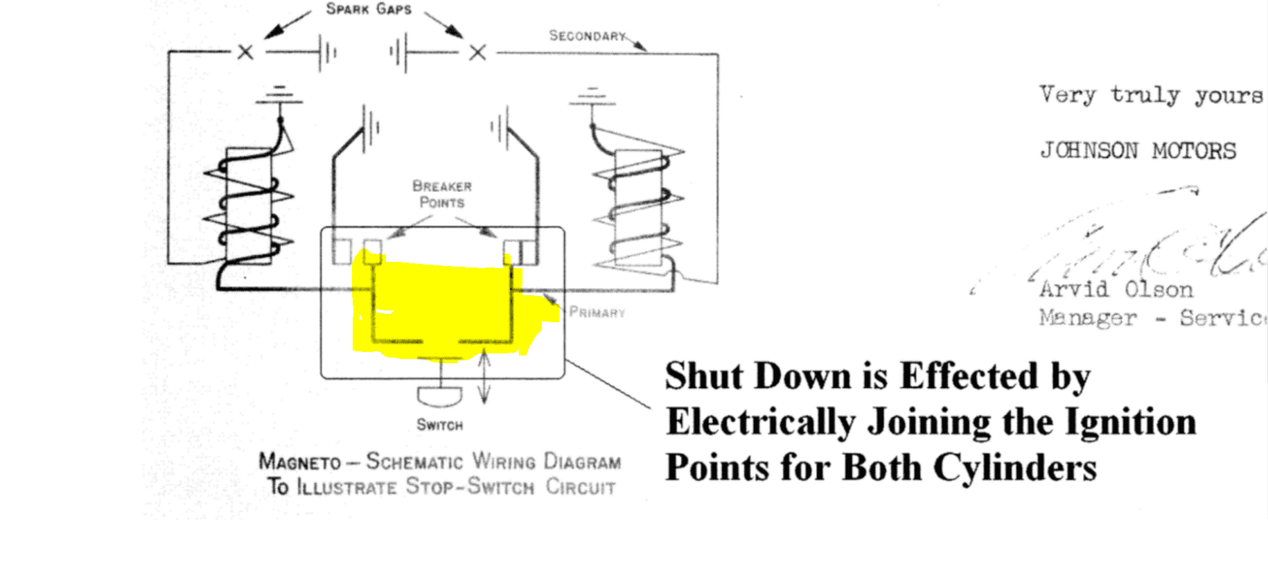
all you need to do to kill the engine is to join both points via a normally open switch.
the kill button (N/O) is or can be mounted on the engine and a pair of M wires sent to the 2 M posts on the key. when OFF the key shorts the 2 BLACK M wires and kills the engine.
True, but I’m thinking he does not have the original stop button on the engine anymore, so it is more of a question just where on the engine the two stop wires (that lead up to the M terminals on the key switch) should be connected… The darn vacuum cut out circuit confuses this issue. True there are two leads hanging off the engine, but they don’t look stock, so no guarantee they are connected properly… I will have to find one of Frank’s wiring diagrams, I was careful to save them when he nicely posted them for us
March 3, 2025 at 11:19 am #294431This wiring diagram should be the same as your motor. Click on it or print it to make it big enough to see:
Dave
March 3, 2025 at 12:09 pm #294434lots of them on …
EVINRUDE JOHNSON Outboard Wiring Diagrams — MASTERTECH MARINE —
and downloading the Red /white bible helps all these oldies
https://watercraftmanuals.com/outboard/johnson/manuals/johnson-302231.htm
the blue circle does not help much lately….
Joining AOMCI has priviledges 🙂
March 6, 2025 at 6:50 am #294483Thanks so much for that.
That’s exactly what I’m going to do.
The only variation in my setup will be using the “Red Plug” from slightly newer OMC outboards. I will however be upgrading the carburetor to one from an earlier 1957/58 35 HP with the electric choke, (I couldn’t resist). Because the Magneto key switch (in the off position) connects the “M” lines I’m putting an E-stop in the lower cowling also using the same “M” lines. I greatly appreciate your assistance in reviewing my plan.
Chris
April 1, 2025 at 9:32 am #295065For all that helped me thank you very much. I’m attaching pics to show I’m almost done. I’ve used the “big red plug” setup from the 70’s – 80’s. (Including current wiring set up.) Note: my pic file size is too large for all so I’ll add in the next post.
April 1, 2025 at 9:42 am #295067Second pic.
April 1, 2025 at 12:25 pm #295089OK, this wiring diagram is more representative of what you have. Your engine does not have those micro switches on the horizontal throttle gear. Yours has the cut out/ground switch on top of the block on the right side.
So, the two M wires from your key switch get connected to the engine as shown in this diagram:
One is connected to one set of points (there should be a black wire coming down from the mag plate that has a “knife connector”. The other “M” terminal lead is connected to the vacuum switch threaded post.
It is super important to remember that these two “M” terminals/leads on your key switch are not to be used for ground leads for any other accessories. If you inadvertently use one of these leads as a ground lead, you will quickly melt one or both of the coils.
By the way, your wiring job looks well thought out and very neat, nice work!
April 2, 2025 at 12:02 am #295099I looked up Seadog 420351-1, and found it for sale for magneto engines BUT it also says the ignition terminal gets 12V when on (for accessories), but not when cranking.
If you have a meter or a test light you can check the connection between the battery and ignition terminals. If they’re connected in any switch position do not connect the ignition terminal to your magneto!
I’d look for a version of the switch with two M (magneto) terminals, that are connected together in the off position, and never to anything else!
http://www.omc-boats.org
http://www.aerocraft-boats.orgApril 2, 2025 at 2:54 pm #295109see diag. however you do it the end result to kill the ignition is to establish continuity between the 2 points .
Joining AOMCI has priviledges 🙂
-
AuthorPosts
- You must be logged in to reply to this topic.