Home › Forum › Ask A Member › Mercotronic Model 98 and Model 9800 Information
- This topic has 47 replies, 10 voices, and was last updated 2 years ago by
29Chev.
-
AuthorPosts
-
March 14, 2023 at 3:17 pm #273876
Hello Antique Outboard Motor Club members. I am new to the site and have logged in as a guest. I wanted to provide some information that may help anyone who owns a Merc-O-Tronic Model 98 or Model 9800. I am not into Outboard Motors but I am into small engines and became acquainted with a Merc-O-Tronic unit in the mid 1970’s while working in a small engine / snowmobile repair shop. I believe that the Merc-O-Tronic is quite a valuable tool for diagnosing older engine ignition problems and since some of the members here may have a unit that may no longer be working properly I wanted to post a few links to the Smokestack Antique Engine Community which may prove helpful to them. I am an electronics hobbyist located in Canada and have been working with a chap in Australia who is into Merc-O-Tronic units and together with the help of the internet we have been able to document and create an actual wiring schematic for the Merc-O-Tronic Model 98 and also for the Model 9800.
Here is a link to the Model 98 information – https://www.smokstak.com/forum/threads/merc-o-tronic-model-98-schematic-and-documentation-information.227737/#post-1917081
Here is a link to the Model 9800 information – https://www.smokstak.com/forum/threads/merc-o-tronic-model-9800-schematic-yellow-circuit-board.227244/
I have also been experimenting along with another member on the Smokestack website (who is also located in Australia) with creating an electronic circuit that may possibly work as a replacement for the mechanical vibrator that is used in the Model 98 and Model 9800 units. Here is a link to that thread on the Smokestack website – https://www.smokstak.com/forum/threads/possible-replacement-for-a-merc-o-tronic-model-98-model-9800-vibrator-suggestion.227436/
It is my understanding that the vibrators do fail and I do not believe that the mechanical ones are being made anymore. Once the schematics were created it helped us understand how the vibrator works in the Merc-O-Tronic units which is slightly different to the way a mechanical vibrator works in an older radio. We have taken the time to hi-lite and document the circuits that are used during each test mode on the Model 9800 – this information can also be viewed in the Model 9800 thread at the link above. The Model 98 unit functions very similar in each test mode but there are a few differences. The Model 9800 is completely powered by the 7.5 volt internal battery for all test modes – it can also be connected to a 12 volt external battery to test some ignition coils that require 12 volts for testing. The Model 98 uses the internal battery for some test but for testing a condenser for value and for leakage and shorts it uses 110 volt AC line voltage.
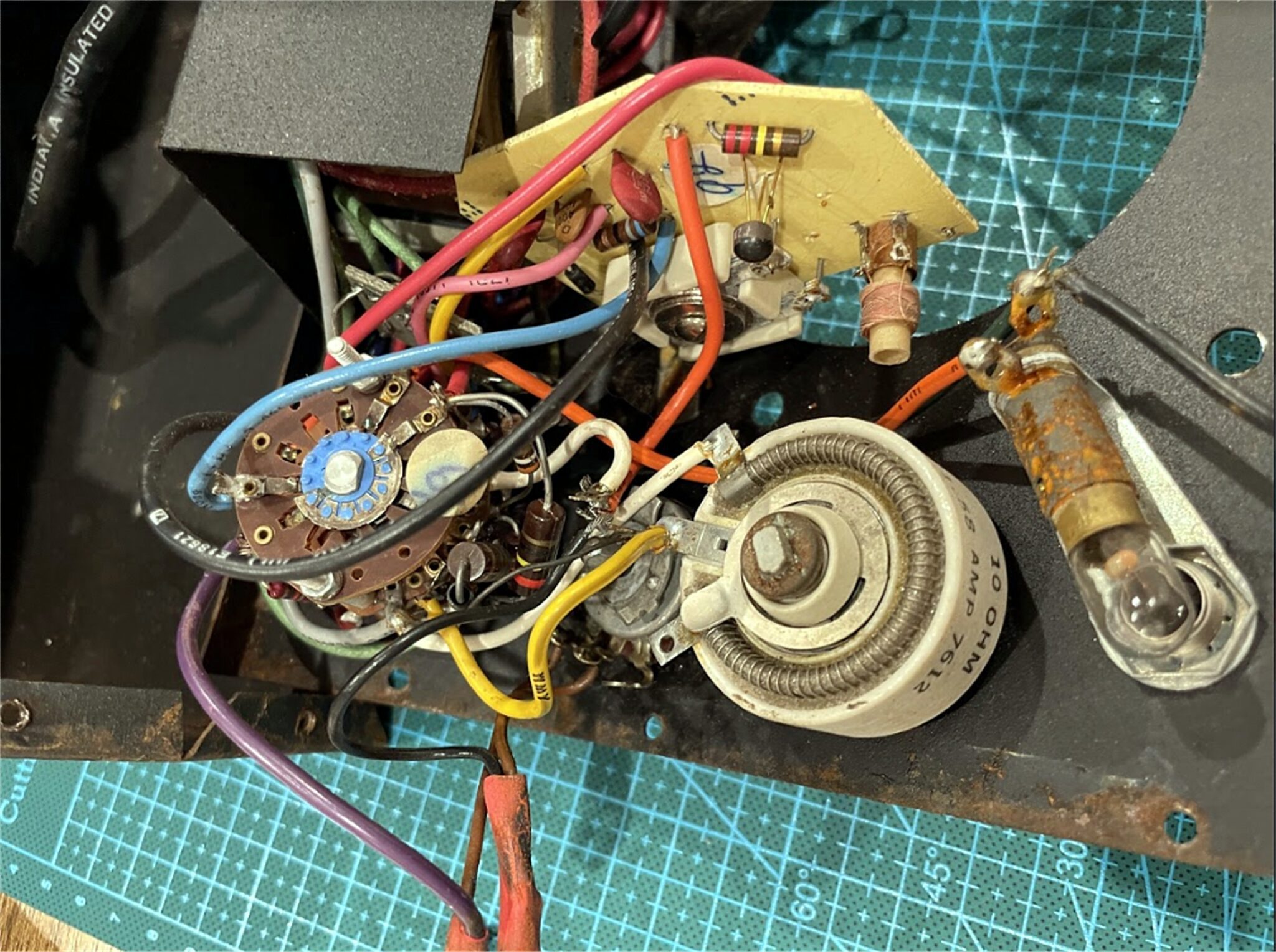
It is out hope by providing this information that people who own a non functioning unit can be able to better understand how it operates and perhaps be able to get their units working again. I have attached a jpeg of the inner workings of thee Model 98 that was documented.
Thank you for allowing me to post this information and if you require more information please visit the Smokestack site and contact me there as I am only logged in as a guest on this site.
1 user thanked author for this post.
March 15, 2023 at 2:08 pm #273917I know little about electronics but would love to build a single circuit for true load testing of outboard coils. The only other function that I would use is condenser testing but good designs are available for that.
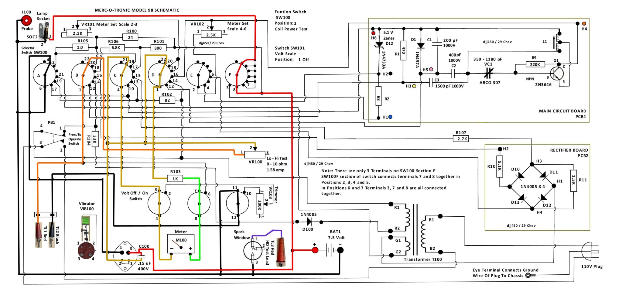
March 16, 2023 at 9:58 am #273967It would not be that hard to create a single circuit to test coils under load but you would have to be careful to keep the input current to a low value so the coil was not damaged similar to how the Mercotronic does it. I have attached a copy of the Model 98 highlighted schematic with the switches set to coil test position as a guide you could use. As you can see it uses a high wattage 10 ohm wire wound variable ohm resistor to control the current going to the coil under test. If you check out the link I posted about the vibrator you can see how a DPDT relay can be configured as an oscillator to replace the vibrator contacts. Another way to open and close the circuit going to the coil under test so it fires repeatedly would be to use an actual point set with a cam operated with a cordless drill. You would need to connect a capacitor that is about 0.15 uF in value and rated for at least 400 volts to protect the contacts on the relay or the point set and to make the coil oscillate properly each time the points open. The capacitor would need to be connected across the contacts as this reduces the arcing as they open and close each time. The variable resistor would need to be rated at whatever voltage and current you will be using to test the coil. A Mercotronic uses a 7.5 volt DC battery to test most coils and the meter is calibrated to supply up to 4 amps of current. Volts times amps equals Watts so you would need a 10 ohm wire wound variable resistor rated at ( 7.5 x 4 = 30) at least 30 watts to handle the current. You can find these shown on Amazon or other sources. https://www.amazon.ca/Variable-Resistor-Rheostat-cer%C3%A1mica-Reostato/dp/B08LDVLMTL/ref=sr_1_1_sspa?crid=2L1HTV1384DFP&keywords=10+ohm+wire+wound+variable+resistor&qid=1678974528&s=hi&sprefix=10+ohm+wire+wound+variable+resistor%2Ctools%2C77&sr=1-1-spons&psc=1&spLa=ZW5jcnlwdGVkUXVhbGlmaWVyPUEyOTdUQlJIVDE5OElOJmVuY3J5cHRlZElkPUEwMTIwNTg3OUtMNkM5Mk9RQU9DJmVuY3J5cHRlZEFkSWQ9QTA4ODE3MDUyREI3SkdKSlNNVU1VJndpZGdldE5hbWU9c3BfYXRmJmFjdGlvbj1jbGlja1JlZGlyZWN0JmRvTm90TG9nQ2xpY2s9dHJ1ZQ== A simple power supply could be five 1.5volt D cell batteries connected in series to obtain the 7.5 volt potential difference – you could make your own holder or purchase a couple that are made to hold four and wire them accordingly jumpering the unfilled portions of the holder. I would suggest using a spring loaded momentary on switch so that you are not tempted to power the coil for any great length of time. A spark plug with a widened gap could be connected to the secondary terminal or plug wire of the coil to serve the same function as the spark window. If the gap is normally about .025″ in the engine spark plug a gap of .075″ should allow the coil to be tested at atmospheric pressure. Since a spark plug inside a cylinder under compression requires a good spark to fire widening the gap should simulate the plug firing under compression. For an amp meter so you know how much current is being delivered to the coil you could try using a digital amp meter (if you have a multimeter with that option that is rated at 10 amps) connected in series in the coil circuit. Some digital ammeters do not like to measure interrupted current circuits with high voltage spikes (which an ignition coil produces – can be as high as 175 volts) very well. I would recommend using a dedicated analog ammeter that is rated 0 – 5 amps – these can be found on amazon or other sources as well. https://www.amazon.ca/uxcell%C2%AE-Rectangle-Current-Analogue-Ammeter/dp/B01LWC6LBD/ref=dp_prsubs_2?pd_rd_w=Ftc54&content-id=amzn1.sym.eb47624e-b593-4e5a-85a6-6fa2045b926c&pf_rd_p=eb47624e-b593-4e5a-85a6-6fa2045b926c&pf_rd_r=W6RPX47NR8WR4MC97MX5&pd_rd_wg=xcBhl&pd_rd_r=d930c3d4-9a64-40d9-9512-af8e64417085&pd_rd_i=B01LWC6LBD&psc=1
As always if you decide to construct such a coil tester do it with safety in mind. The variable resistor can become quite warm or even hot during a test and can burn skin. Ignition coils are designed to develop high voltage (20000 volts or more usually) that can shock or even kill so use the appropriate rated wiring for the primary and secondary circuits. These are just some suggestions to consider – it is up to you to determine if you have the necessary skills to construct a tester that will operate safely for you and anyone else that may be tempted to use it. Hope this provides some helpful information for you.
1 user thanked author for this post.
March 16, 2023 at 12:24 pm #273974Thanks “29 Chev” for sharing your work here. I frequent SmokeStak also, and have been following your thread. Fortunately my 9800 works fine. My 7.5 V battery is 8 years old and about ready for a change. After quite a search I found a supplier here (S-E MI) that can get them (Ray-O-Vac #903). Your suggestion of five “D” cells will give the 7.5 V . but will it provide sufficient amperage?
Joe B ( 31 Ford)
March 16, 2023 at 2:13 pm #273983Thanks “29 Chev” for sharing your work here. I frequent SmokeStak also, and have been following your thread. Fortunately my 9800 works fine. My 7.5 V battery is 8 years old and about ready for a change. After quite a search I found a supplier here (S-E MI) that can get them (Ray-O-Vac #903). Your suggestion of five “D” cells will give the 7.5 V . but will it provide sufficient amperage?
Joe B ( 31 Ford)
Hi Joecb,
I cannot tell you for sure – it would depend on the coil being tested , the length of time it was being tested and how much the current being fed to it was limited by a resistance unit. I think that for a 10 – 15 test second test period one could probably establish whether a coil is firing reliably or not using 5 D cells which I believe is what the person looking to construct a single circuit to load test a coil was looking for – one would have to try it and see the results. If I am wrong in my understanding of that comment I apologize and of course a larger current source would be a good idea but that would add to the cost of a coil testing circuit. To determine if a coil under test is actually meeting a manufacturers specification such as is listed in the Mercotronic manuals is a different situation. One would need to first determine the specification and then construct the identical circuit that the Mercotronic (or another manufacturer) uses to test it properly with the correct battery source capable of delivering the proper current. Since we do not know the actual meter specs that was used in a Mercotronic that could prove to be a challenge. During my experimenting on making an electronic version of the vibrator used in a Mercotronic I was using a 12 volt automotive ignition coil that was capable of drawing over 4 amps at 13+ volts using a 10 amp 12 volt battery charger to supply power to the coil without having a current limiting resistor in the circuit. I was also able to fire the same coil with a good spark reliably using a widely gapped spark plug at a voltage level of 7.5 volts using a bench top variable voltage power supply that was only capable of delivering 1 amp of current by limiting the current using a 10 ohm variable resistor – the wire wound resistor I had was light duty and got hot quickly which is why I specifically stated to get one that is rated for the wattage I mentioned. As the resistance value of the current limiting resistor is decreased the current draw of the coil will naturally increase and that could drain the 5 D cells quickly to a point where they would no longer supply adequate current flow. The suggestion I made of using 5 D cells was just that – a suggestion of just one example of how a 7.5 volt potential difference level can be achieved for a reasonably low cost since the 7.5 volt style batteries that are used in a Mercotronic are no longer easy to find or inexpensive. Two sets of 5 D cells could also be connected in parallel to produce double the current and still maintain a 7.5 volt level. If the current was found to be lacking there are also commercial power supplies that can be purchased with adjustable or fixed voltage levels and capable of producing up to 5 or 10 amps if someone wants to spend the money. This would also be dependent on how many ignition coils someone is testing each day, week or month. In my experience most people who tinker with antique engines have high expectations and (like me) very shallow pockets which makes a compromise like having a less than adequate current source a reality.
March 16, 2023 at 4:14 pm #273996I just ordered an injector tester for 35$ on Amazon… I plan to try it out on a coil to see I can get the coil to spark.
the unit has variable pulse lengths for injectors but I figured the slow pulse rate could energize a coil . if not well to bad .
Condensers.. I test those with Mr.Mohat (western region aomci articles) home made box… works great 🙂
Joining AOMCI has priviledges 🙂
March 16, 2023 at 5:46 pm #274001An AC adaptor like this might work for a Mercotronic or a standalone coil tester using a circuit similar to the Mercotronic as it is rated at 7.5 volts 6 amp output. Would have to adapt the connector on the end and the price does not include the cord that plugs into the wall outlet. Just another option that may be suitable if portability during testing is not a necessity.
https://www.digikey.ca/en/products/detail/mean-well-usa-inc/GST60A07-P1J/7703710
March 16, 2023 at 10:03 pm #274019
29Chev,
The merc o tronic I have now works fine
“except” when testing a coil the meter readings
are low compared to others units I’ve had
testing the same coil. Your thoughts?
Tubs.A "Boathouse Repair" is one that done without having tools or the skills to do it properly.
March 16, 2023 at 11:57 pm #274024Thanks guys for all the info and suggestions. At this time I do have a Ray-O Vac #903 – 7 .5 Volt battery coming, price not too bad about $19. However for the long term , it would be nice to have a 7.5 DCV power supply. Any thoughts as to any potential issues with the wave form from a typical power supply as opposed to a true DC from a battery affecting the Mertronic function?
Joe B
March 17, 2023 at 12:13 am #274026I use a 7.2-volt battery and charger from remote toys at least 5500 price around $30.00 and last a life time.
1 user thanked author for this post.
-
AuthorPosts
- You must be logged in to reply to this topic.