Home › Forum › Ask A Member › Mercotronic Model 98 and Model 9800 Information
- This topic has 47 replies, 10 voices, and was last updated 2 years ago by
29Chev.
-
AuthorPosts
-
March 17, 2023 at 8:11 am #274033

29Chev,
The merc o tronic I have now works fine
“except” when testing a coil the meter readings
are low compared to others units I’ve had
testing the same coil. Your thoughts?
Tubs.What model is the Mercotronic unit you have?
March 17, 2023 at 8:24 am #274034Thanks guys for all the info and suggestions. At this time I do have a Ray-O Vac #903 – 7 .5 Volt battery coming, price not too bad about $19. However for the long term , it would be nice to have a 7.5 DCV power supply. Any thoughts as to any potential issues with the wave form from a typical power supply as opposed to a true DC from a battery affecting the Mertronic function?
Joe B
As long as the power supply you get has a 7.5 volt (or close) DC output and has some filtering built into it such as for use with a computer or other electronic equipment it should work fine. Mercotronic did offer a AC to DC power supply that was designed to actually fit inside the Mercotronic and had a selector switch that could be set for a 7.5 volt or 12 volt output. It also had a 110 volt receptacle so it could supply power to the Model 98 which requires 110 volts AC to perform some of the condenser tests – condenser value and condenser leakage and short. The unit we documented has an output voltage of 8.2 volts in the 7.5 volt setting and 12.7 volts in the 12 volt setting with nothing connected to it. A picture of it can be viewed in the 5th post of this thread on the Smokestack website. https://www.smokstak.com/forum/threads/merc-o-tronic-model-98-schematic-and-documentation-information.227737/
March 17, 2023 at 9:15 am #274035Thanks guys for all the info and suggestions. At this time I do have a Ray-O Vac #903 – 7 .5 Volt battery coming, price not too bad about $19. However for the long term , it would be nice to have a 7.5 DCV power supply. Any thoughts as to any potential issues with the wave form from a typical power supply as opposed to a true DC from a battery affecting the Mertronic function?
Joe B
As long as the power supply you get has a 7.5 volt (or close) DC output and has some filtering built into it such as for use with a computer or other electronic equipment it should work fine. Mercotronic did offer a AC to DC power supply that was designed to actually fit inside the Mercotronic and had a selector switch that could be set for a 7.5 volt or 12 volt output. It also had a 110 volt receptacle so it could supply power to the Model 98 which requires 110 volts AC to perform some of the condenser tests – condenser value and condenser leakage and short. The unit we documented has an output voltage of 8.2 volts in the 7.5 volt setting and 12.7 volts in the 12 volt setting with nothing connected to it. A picture of it can be viewed in the 5th post of this thread on the Smokestack website. https://www.smokstak.com/forum/threads/merc-o-tronic-model-98-schematic-and-documentation-information.227737/
I have used this power supply with good results.
It was only $15.00 but that was over 10 years ago.
Do a search for-
Mean Well New GST40A07-P1J 7.5V Power Supply.
Tubs

A "Boathouse Repair" is one that done without having tools or the skills to do it properly.
March 17, 2023 at 9:24 am #274036
29Chev,
The merc o tronic I have now works fine
“except” when testing a coil the meter readings
are low compared to others units I’ve had
testing the same coil. Your thoughts?
Tubs.What model is the Mercotronic unit you have?
Afraid you would ask that. Its an earlier model 88
with a motor and points instead of the vibratory tube.
Tubs

A "Boathouse Repair" is one that done without having tools or the skills to do it properly.
March 17, 2023 at 3:13 pm #274064
29Chev,
The merc o tronic I have now works fine
“except” when testing a coil the meter readings
are low compared to others units I’ve had
testing the same coil. Your thoughts?
Tubs.What model is the Mercotronic unit you have?
Afraid you would ask that. Its an earlier model 88
with a motor and points instead of the vibratory tube.
Tubs
I would love to see some pictures of that unit internally – an older unit but still quite handy to have. Since your unit uses a contact set rather than a vibrator I am not familiar with it – the chap I have been working with in Australia does have a model 88 that uses a contact set and we hope to document it as time permits.
Having said that I am familiar with the original patent documentation of the original Mercotronic and it shows a contact set that is opened and closed with a DC motor. I am going to post the information that I have discovered about it as I am guessing the model 88 is similar schematic wise in coil test mode. It will be up to you to determine if your unit is similar.
I have attached a highlighted schematic of it and a pdf that should include the schematic and the text I am about to post so you can download and print it off easily if the information looks useful to you. It may also help others with a better understanding of how the unit functions during a coil test.
Mercotronic Original Schematic Drawing Coil Test Mode Information
Note: This information is provided as is – Use At Your Own Risk And Expense
Components in play
B1 – 7.5 volt battery
C1 – Capacitor to reduce arcing at contact set and prolong ignition coil under test oscillations
CS1 – Contact set to make and break circuit that provides current to red test clip TL1
L1 – Lamp to indicate S1 is in on position and motor should be running
M1 – Meter to display amount of current flowing to ignition coil under test
Motor – operates cam to open and close contact set CS1
R7 – High wattage Resistor to act as shunt for meter M1
S1 – 5 Position Switch with 4 segments
Spark Window –Displays spark across electrodes
TL1 – Red test clip connects to ignition coil primary of coil under test
TL2 – Black test clip connects to ground terminal of coil under test
TL3 – Large red test clip connects to secondary terminal or plug wire of ignition coil under test
VR1 – Variable resistor to control amount of current supplied to ignition coil under test
In the ignition coil test mode the mulit-position selector switch S 1 is set to position 1. This supplies battery power from the positive terminal of the battery B1 to the DC motor which starts to turn operating a cam that opens and closes the point set CS1. The indicator lamp L1 will be illuminated. Current will also flow from the battery positive terminal to one side of resistor R7 and the positive terminal of the meter M1. Current flows through resistor R7 to the contact set CS1, the negative terminal of the meter M1 and to the one side of the capacitor C1. Current will flow through the variable resistor VR1 to the red test lead clip TL1 which is connected to the positive terminal of the ignition coil under test. Current will flow through the coil primary winding to the black test lead clip TL2 which completes the circuit to the battery B1 negative post.
As the motor rotates the contact set CS1 will continuously open and close the circuit going to the coil under test acting like an off on switch. With the contact set closed the primary winding of the ignition coil will become electrified and when the contact set opens the majority of the trapped electrical energy in the primary coil winding will be transferred to the secondary winding of the coil under test resulting in a spark being produced across the electrodes in the spark window if the current being supplied to the primary winding of the coil under test is high enough.
As the variable resistor VR1 is rotated from left to right the resistance value of VR1 will decrease resulting in more current to flow through R7 and the meter coil M1 – these two components may be viewed as two resistors connected in parallel. Resistor R7 is acting as a shunt resistor in parallel with the meter coil winding. Since resistor R7 is a fixed value it will only allow a fixed amount of current to flow through it to the primary winding of the ignition coil under test in a given time interval. The rest of the current flow will happen across the coil winding of the meter M1 and as the value of VR1 decreases the amount of current flowing through the meter coil will increase in proportion. This will result in the needle movement of the meter increasing or decreasing depending on the resistance value of the variable resistor VR1.
In the Mercotronic model 98 and 9800 the value of the variable resistor is approximately 10 ohms so I would guess that the value of VR1 is probably similar but this is only a guess. The value of R7 is not given and because the meter circuit is set up differently in the model 98 and 9800 I do not know what the value of R7 should be in the original schematic. If your unit looks similar to the schematic connection wise you should be able to find a resistor equivalent to R7 as one end of it will probably be connected to the contact set CS1, a capacitor C1 and a switch terminal corresponding to S1B terminal 1 . My guess is the capacitor C1 is probably a value of 0.15 uF and rated for 400 volts DC. The resistor may be mounted on the multi position switch on a couple of terminals S1B terminal 1 and S1C terminal 1 and the other end of it will probably connect to the positive terminal of the meter M1 and to the positive terminal of the battery B1 when the switch is set to position 1. The resistor should have four or five colour bands around it – three should indicate the value and the fourth and possibly fifth should indicate the tolerance. This resistor may be out of spec and resulting in the meter reading being off.
With the battery disconnected and the switch set to the coil position test you can check the highlighted sections of the schematic to verify that there is no resistance between any two connection points. In a perfect world the reading should be zero but any reading of 0.2 ohms or less should be acceptable. If you have more resistance than 0.2 ohms then there is probably a connection problem between those two points. For example if you connected one ohmmeter lead to S1B terminal 1 and the other to the negative terminal of the meter you should get a reading of 0.2 ohm or less. You can check all contact points in a highlighted colour section of the schematic to verify that the resistance between them is acceptable. For example if you connect one lead of an ohmmeter to the red test clip TL1 and then touch the other lead of the ohmmeter to any spot in the blue highlighted section of the schematic (S1A bottom terminal, S1A terminal 1 and the one terminal at VR1 you should get a reading of 0.2 ohms or less. A higher resistance reading indicates a connection problem. Similarly the orange, green, red and black sections of the schematic can be checked for resistance problems.
As stated a connection problem or the shunt resistor being off in value may be why your unit is not displaying the proper meter reading of current flow during a coil test if the meter works ok in the other test modes. Another problem could be that capacitor C1 may have changed in value or be partially shorted given the age of your unit if they are original. You may also want to check the resistance value of the contact set when closed as this could also add resistance to the current flow going to the coil primary winding resulting in reduced current flow across the meter coil since the value of R7 and the meter coil connected in parallel is calibrated to work with minimal resistance at the contact set.
I have tried to keep the electronic terms to a minimum and hope this helps and is easy to understand – if you have any questions please advise.
March 17, 2023 at 6:35 pm #274071Joe, I use a 7.5 volt DC power supply for a laptop, good clean power…. works wonderfully… Added one of those silly connectors inside the case and plug it in when needed.
http://www.richardsoutboardtools.com
classicomctools@gmail.comMarch 17, 2023 at 8:47 pm #274072
I have had 3 model 88’s.
Two have 5 setting knobs. The other has 4.
Top one I gave to a friend of mine.
He lives 1400+ miles away so
I don’t have access to that one.
Middle one I let a friend borrow.
He passed away and I’m not
getting that one back.
I do have the bottom one.
I have compared readings to see how
close one was to the other on several
coils and that is how I know the one I
still have reads low. Most of the coils
I test I don’t know what the readings
should be so it really doesn’t matter.
I would repair it if I could.
Here are some pictures of the inside
of the one I have that reads low. I
appreciate your detailed explanation
of what could possibly be the problem
with mine but my electrical skills only
qualify me to change light bulbs.
Tubs

A "Boathouse Repair" is one that done without having tools or the skills to do it properly.
March 17, 2023 at 11:37 pm #274073
I have had 3 model 88’s.
Two have 5 setting knobs. The other has 4.
Top one I gave to a friend of mine.
He lives 1400+ miles away so
I don’t have access to that one.
Middle one I let a friend borrow.
He passed away and I’m not
getting that one back.
I do have the bottom one.
I have compared readings to see how
close one was to the other on several
coils and that is how I know the one I
still have reads low. Most of the coils
I test I don’t know what the readings
should be so it really doesn’t matter.
I would repair it if I could.
Here are some pictures of the inside
of the one I have that reads low. I
appreciate your detailed explanation
of what could possibly be the problem
with mine but my electrical skills only
qualify me to change light bulbs.
TubsSome very nice and tidy units you have there. Much cleaner than mine which I’ll be working on restoring in the future. Interesting see the 5th knob for the condenser capacity calibration the model 98 does not have that, the transformer does all the work and can’t be adjusted. My early unit attached below Serial # starting at 1000
March 18, 2023 at 8:56 am #274080
Even though the unit you posted a picture of
doesn’t have the 5th knob its still an 88.
98’s have a vibrator tube instead of points.
Tubs.

A "Boathouse Repair" is one that done without having tools or the skills to do it properly.
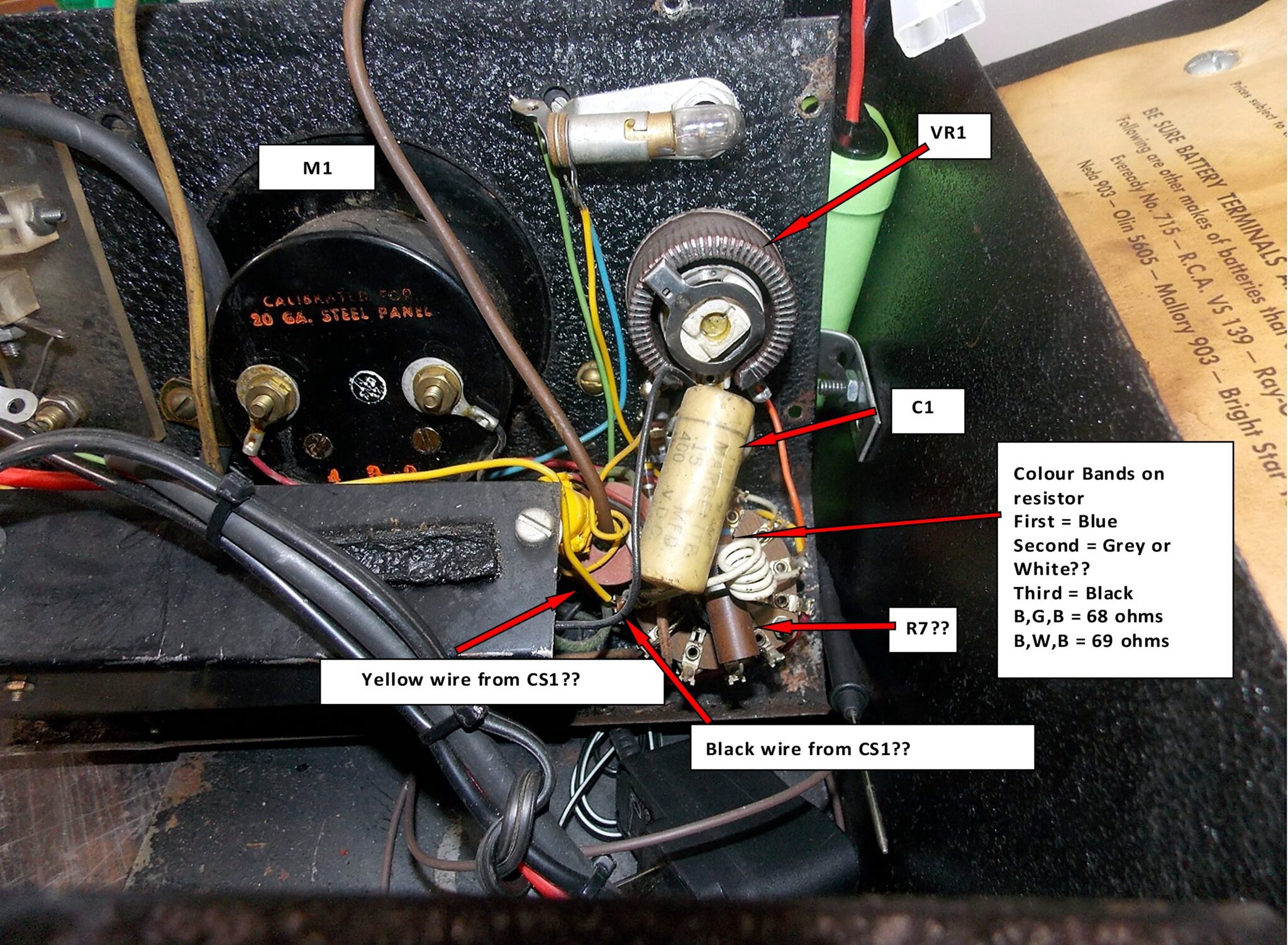
March 18, 2023 at 11:09 am #274082Thank you for sharing the pictures.
I assigned some labels to a few components that may help you test and perhaps fix your unit. Being able to change a light bulb is a step in the right direction (we all started there at some point in our lives as far as learning electrical goes) and perhaps you can find a friend or relative that may be able to help you with measuring a couple of resistance values. From what I am seeing the coil test portion of the original schematic appears to be similar to your unit but cannot say for sure. I am thinking that the shunt resistor R7 is the large resistor connected to the two terminals on the function switch as I have labelled it but cannot say for sure which is why there are the question marks. From what I can tell the colour bands are blue, grey or white and black which would indicate a value of 68 or 69 ohms of resistance. If you have a multimeter you could check the value of it – make sure the power supply is disconnected and set the selector switch to the off position so the meter is not part of the circuit. You should get a reading of 64 to 74 ohms across the two resistor leads. If it is less than the lower reading then it could be the reason the meter is low since too much current would be allowed to flow through it and not enough will go through the meter coil. Looks like the capacitor C1 should have a value of 0.15 uF 400 volts DC. You could also check the value of it the same way as testing a condenser if you put a piece of paper in between the contacts on the point set and then measuring across the leads of the condenser. I would suggest using a separate capacitor tester to do this and again have the power supply disconnected and set the selector switch to the off position. If the capacitor is partially shorted it could also make the meter read low as well as not accurately perform a coil test – given the age of the unit that is a possibility. There could also be a problem with resistance caused by tarnish or grease at one of the selector switch contacts going to the meter when the selector switch is set in the coil test position. These are the best suggestions I can offer to you – I hope they help.
-
AuthorPosts
- You must be logged in to reply to this topic.