Home › Forum › Ask A Member › mercury 120hp force straight4 trigger question
- This topic has 8 replies, 3 voices, and was last updated 4 years, 4 months ago by
 Beno.
Beno.
-
AuthorPosts
-
July 4, 2021 at 2:10 pm #241948
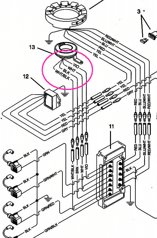
I’m flowcharting the electrical diagram for my 120hp Mercury force.. I’m looking at the 4 trigger wires. in the attached diagram they are
violet (V) white (W) Black (B) white/black (WB) . circled in Pink..
ok fair enough 4 wires for 4cyls… but I can see no way the trigger is grounded so the action the trigger/wires must be making could only be closing/shorting against each other in a creative (this is my assumption????)if that’s true.. then what is the correlation to the firing order? for example. if it’s firing order is 1-3-2-4 (as I’ve been told)
is it shorting like??? this?:
1 – (V+W)
3 – (W+B)
2 – (B+WB)
4 – (WB+V)
??????? or am I WAY off?and to make things more complicated.. every computer system I’ve worked on, designed or fixed ran on 3.3v, 5v, or 12v. nowhere in this diagram is the CDI computer connected to the 12v of the boat battery..(except backwards thru that power regulator..) the only power source I see is the flywheel? which should be voltage in the thousands??? how can that computer even be working? does a Force CDI stay running if you pull the battery?
July 4, 2021 at 3:50 pm #241966That’s why Mercury calls it “ADI,” for alternator-driven ignition. The flywheel generates everything it needs for ignition. As for the trigger wires, my Force-speak is a little old but you should find that you have continuity between two pairs of those wires. There are two small coils in the trigger assembly. As the flywheel turns, magnets pass by these coils and generate a small amount of electricity. The direction of the current changes as the magnets approach, then pass, the coils. This change in direction is taken into consideration by the switch box (or power pack, for OMC guys) and allows the switch box to know which coil to fire. The trigger generally only produces a few volts and is usually about the last thing wrong with ADI systems.
Long live American manufacturing!
July 4, 2021 at 3:56 pm #241967I’m not sure if you have a running problem or were just curious. I will say this, though: For a running problem on a Force 120, the very, VERY first thing to do is check compression. They used to lunch pistons faster than an OMC cross-flow.
Long live American manufacturing!
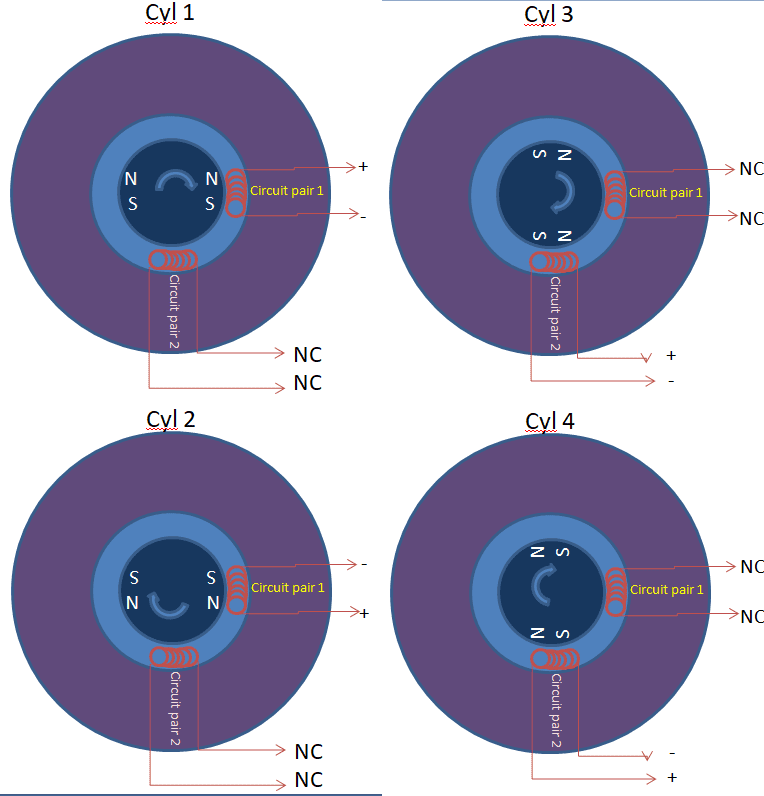
July 6, 2021 at 12:25 am #242048ok.. Now I kind of see. It’s not a trigger that shorts (like points do).. its’ a trigger that creates a small signal current and informs the CDI box via the 4 wires. hmm
so with 4 wires you have 4 possible combinations
(circuit pair 1),(circuit pair 2)
cyl 1:(+,-),(nc,nc)
cyl 3:(nc,nc),(+,-)
cyl 2:(-,+),(nc,nc)
cyl 4:(nc,nc),(-,+)assuming there are 2 magnets inside the center of the flywheel, this is what I theorize.. see attached pic.
think this is correct?July 6, 2021 at 5:49 am #242054I think there is only one “magnet,” which pretty much encompasses the whole inner part of the flywheel center. As the N side of the magnet approaches one trigger coil, current builds in one direction. As it passes the coil, the current direction changes and it flows in the other. 180 degrees of flywheel rotation from this event, the same thing happens; but instead of the N pole approaching and passing, this time it is the S pole. The different pole means the current starts and finishes going in opposite directions from what the N pole would create. The switch box sees all this and has circuitry that will fire each coil, based on which way the change of direction occurs. My apologies; I am just a mechanic, not an engineer, by any stretch.I am sure an engineer could explain it better.
Long live American manufacturing!
-
This reply was modified 4 years, 5 months ago by
billw. Reason: typo
July 6, 2021 at 11:39 pm #242128ok thanks. I will check that out.. I like to have a complete understanding of my technology before I get to far into it. the various kinds of ignition have always been interesting to me.
Currently I have a 120hp mercury straight 4 force that my recollection was last year only 2 cyls were firing..
I checked the trigger resistance and I think I got 850ohms per circuit. so I’m guessing the trigger is good.
the boat hull numbers show 1996, but who knows if the engine is original or not.Later this week I’ll get up that way and check that ohms at the stator connectors.
July 7, 2021 at 5:47 am #242132I dug out my Force manual. In “theory of operation,” it says, “the inner hub also has a set of magnets that generate AC voltage.” So, it implies I’m wrong about one magnet; but it doesn’t really elaborate much more than that.
Book says trigger resistance is between the violet and white wires and between the brown and black wires; and it should be between 700 and 1000 ohms. Your 850 is pretty darn perfect….DVA running tests are the real way to go on these ignitions.
Long live American manufacturing!
July 7, 2021 at 9:41 am #242145CDI Electronics has a great troubleshooting guide for all the electronic ignitions. I have used it on a few small Mercurys and I like their products. Check their web site out.
cdielectronics.com.July 21, 2021 at 5:58 pm #243401Alright, Thanks for the help everyone.
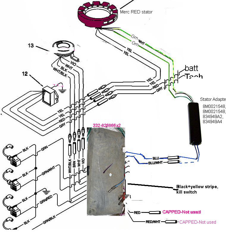
I completely mapped out the ignition system on a SportJet 120 with Red-Stator.. ordered a new CDI box and I now Have spark on all 4 cylinders!
I made a fixed graphic of how my engine “REALLY” works.. I never did find this online anywhere so I made it..now I have a new and different issue which I will start in a new thread.
Ben
-
This reply was modified 4 years, 5 months ago by
-
AuthorPosts
- You must be logged in to reply to this topic.


