Home › Forum › Ask A Member › OMC Kill-switch question
- This topic has 25 replies, 5 voices, and was last updated 9 months, 2 weeks ago by
fleetwin.
-
AuthorPosts
-
July 1, 2024 at 5:03 pm #288774
Just a wild thought. Is it possible that at the higher RPM the points are opening and closing so fast that the ground is not actually there long enough on either cylinder to stop the engine? If you hook up both coil wires going to the points to a switch to ground, will this work?
July 1, 2024 at 9:07 pm #288782About The flywheel—–
A uniiversal mag flywheel has one magnet passing by the coils alternately.. A low tension flywheel has a second magnet 180 degrees apart..Theory is that he has a flywheel with two magnets. While he is pressing the button he is trying to ground the active coil through the inactive one except the inactive one is not dead. That extra magnet is passing by it and generating electricity in it. So he is not grounding it but connecting it to a second voltage source.
We should hear back from him soon.
July 3, 2024 at 1:24 pm #288814All great points** , and I appreciate them! But at the risk of sounding like an arrogant know-it-all (most certainly NOT my intention), I don’t think that’s the issue. The engine is a “badged” ’57 Golden Javelin, but it was made from the carcasses of 2 of those + a ’59 Gale Sovereign (35DE11, which is a damn-near identical engine). It’s got the Gale’s powerhead, mag plate & flywheel (universal, just 1 magnet). It runs great. Believe it or not, we water ski with it!
(** no pun intended!!! 🙂 )
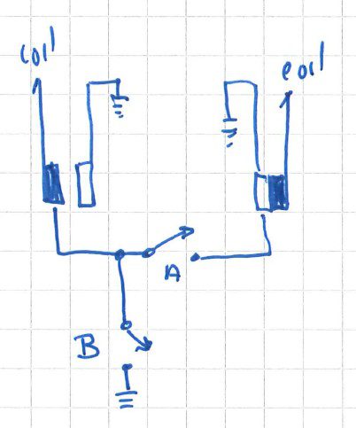
Gary Haight’s post above…grounding the points simultaneously…is very much in line with my proposed idea (see my schematic in my original post). I can’t see how that proposed schematic wouldn’t absolutely accomplish the task, inasmuch as the points would be tied together + individually grounded. “Belts & suspenders”.
Still, the greater question remains: I shouldn’t have to! The stock circuit (simply joining the 2 points together to each other) should, by all rights, kill the engine dead. With two separate ohm meters simultaneously attached to the points, and with the kill switch closed, I can (manually) turn the crankshaft 360 degrees, and the reading to ground is zero. But to Gary’s point, at high speed, is everything just happening too fast? The logic of the circuit says “no”, but indeed, reality might be a different matter. Is that possible?
The other side of the equation is this: If I’m at the wheel of my boat, and I need to kill the engine immediately, how hard is it to yank back on the throttle, since the switch works at lower RPMs?
Puzzled, I remain,
July 3, 2024 at 1:38 pm #288815Hang on…wait a sec….back up!
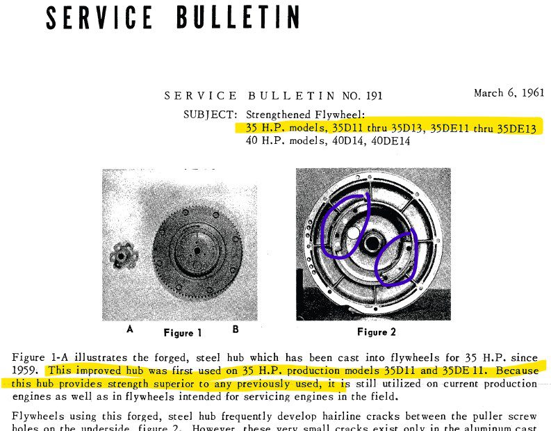
I said the Gale flywheel had one magnet, and I sure think that’s true. However, I just pulled out an old service bulletin from my files, and I’m beginning to have doubts.
This bulletin is about flywheel cracks, but never mind that….does this show 2 magnets? Is the “Superior strength” accomplished by 2 magnets? Looks like I may need to pull the flywheel (again 🙁 ) to know for sure.
July 3, 2024 at 2:46 pm #288821I think you will find that in this case that second magnet is not a magnet at all just a dummy for balancing. Anyhoo, I don’t think they ever made a two magnet flywheel that would fit a 35 crankshaft. So we can put that theory to rest.
July 3, 2024 at 3:01 pm #288822After I posted, my dinky lil’ brain said “hmmm…or maybe that’s just a counterweight“. It was a good theory, though…and I very much appreciate your input!
The quest for knowledge continues.
July 3, 2024 at 4:31 pm #288827Did you consider Frank’s advice about the darn vacuum switch being improperly wired? You could always just try bypassing the vacuum swith/mercury connectors, etc and connect the stop switch directly to the stop leads coming out of the mag plate to test Frank’s theory. To me, Frank’s theory makes the most sense.
But, on the other hand, wiring up a switch like you propose would get the job done for sure, but like you say, you shouldn’t have to. A switch like that will add complexity, and more opportunity for moisture, shorts to ground, arcing though.
I will go back and reread, perhaps you have addressed this and I missed it.
July 3, 2024 at 4:34 pm #288828Btw wrong flywheel may not be a crazy guess.Any bets?
You are right Frank…Mid 70s model 40hps used the beloved low tension ignition, so wondering if that flywheel could be swapped. But, it seems unlikely that things would line up and any spark would be produced at all. NJ says he looked at the flywheel, and the second bump inside is indeed just a counter weight, not a magnet.
July 8, 2024 at 10:28 am #288945Long, hot, humid weekend….too hot to be tearing into an engine, but whatchagonnado, right?
– Flywheel off…it’s a 1-magnet wheel. That lays that theory to rest.
– Points…at any given moment in one revolution of the crank, at least one point is grounded to the mag plate (and the mag plate is well grounded to engine frame…zero ohms). Absolutely, joining these points to one another should kill the engine.
– Vacuum switch / points are wired correctly.
I put it all back together and fired it up. Runs great, can’t wait to get to Maine in a few weeks and enjoy some lake time. But the kill switch (on the dash of the boat) doesn’t kill the engine. Stutters & runs like crap, but kill? Nope. I figured maybe it was the wiring from my transom to the dash. Rung everything out, and it’s fine.
So the next step was to hook up 2 switches directly to the engine to see if the issue was on the engine or elsewhere….i.e. “Am I looking in the right place?”
Switch “A” is a conventional “tie the points together” kill switch, wired directly to the points. Switch “B” is a supplemental switch to test my theory in the original post.
Fire up the engine, increase the revs a bit, and close switch “A”. As with the similarly-connected switch on the boat’s dashboard, the engine stutters & runs poorly, but doesn’t shut off.
With switch “A” still closed (and the engine stuttering), I closed switch “B”, thereby tying the still-joined-points directly to ground. The engine died instantly.
While I remain curious as to why switch “A” (alone) didn’t accomplish the task, I’m perfectly happy to change the kill switch on the dashboard to a DPST switch as shown in my original post…now that I know such will accomplish the goal.
July 8, 2024 at 12:13 pm #288952very odd. the additional A switch ground should not be necessary …… if the ground referrence on the points is at the same ” ground” potential .
your conclusion “points” to an inadequate grounding of the ignition points when closed during the low side of the lobe . . .
if you locally kill the ignition with a normal open push switch mounted somehwere close to the points …..thereby joining the points
does it die ?
if not … the problem is strickly engine side located
btw your sketch seems wrong wires should link both point grounds not one to the ground side (right one) and the left one to the point side .
Joining AOMCI has priviledges 🙂
-
AuthorPosts
- You must be logged in to reply to this topic.


