Home › Forum › Ask A Member › Problems gapping points on QD-19
- This topic has 27 replies, 14 voices, and was last updated 3 years, 11 months ago by
 frankr.
-
AuthorPosts
-
May 5, 2020 at 11:46 am #202068
I just got done staring at my points. If I remove the adjusting screw, what am I prying at/against. I’m kinda lost there???
May 5, 2020 at 12:17 pm #202073Verify that the rivets in the point sets are tight, and parts are not loose. I had this problem a few years back on a new set of points.
T
May 6, 2020 at 9:49 am #202175I just got done staring at my points. If I remove the adjusting screw, what am I prying at/against. I’m kinda lost there???
The adjusting cam limits the range of adjustment. Remove it and using your feeler gauge just set the gap and then tighten the set-screw (the one with the wave washer under it). You may need to repeat a couple of times to get it perfect.
-
This reply was modified 3 years, 11 months ago by
 seakaye12.
May 6, 2020 at 10:35 am #202182Removing the adjusting cams sounds like the “magic” that I’ve been missing. I bought a motor that had them removed and I thought it was just sloppy service work by some past owner – now it’s making more sense why.
May 6, 2020 at 10:39 am #202183If I’m reading right, remove the eccentric and tighten the hold down? I’ll give it a try
May 6, 2020 at 11:58 am #202191Hey, just a minute. In your opening post you say you are using a meter with tone? Well, if all the wires are connected to the points while setting the timing, you wont get a tone as there will always be continuity. First thru the points to ground and then thru the coil to ground when the points open.
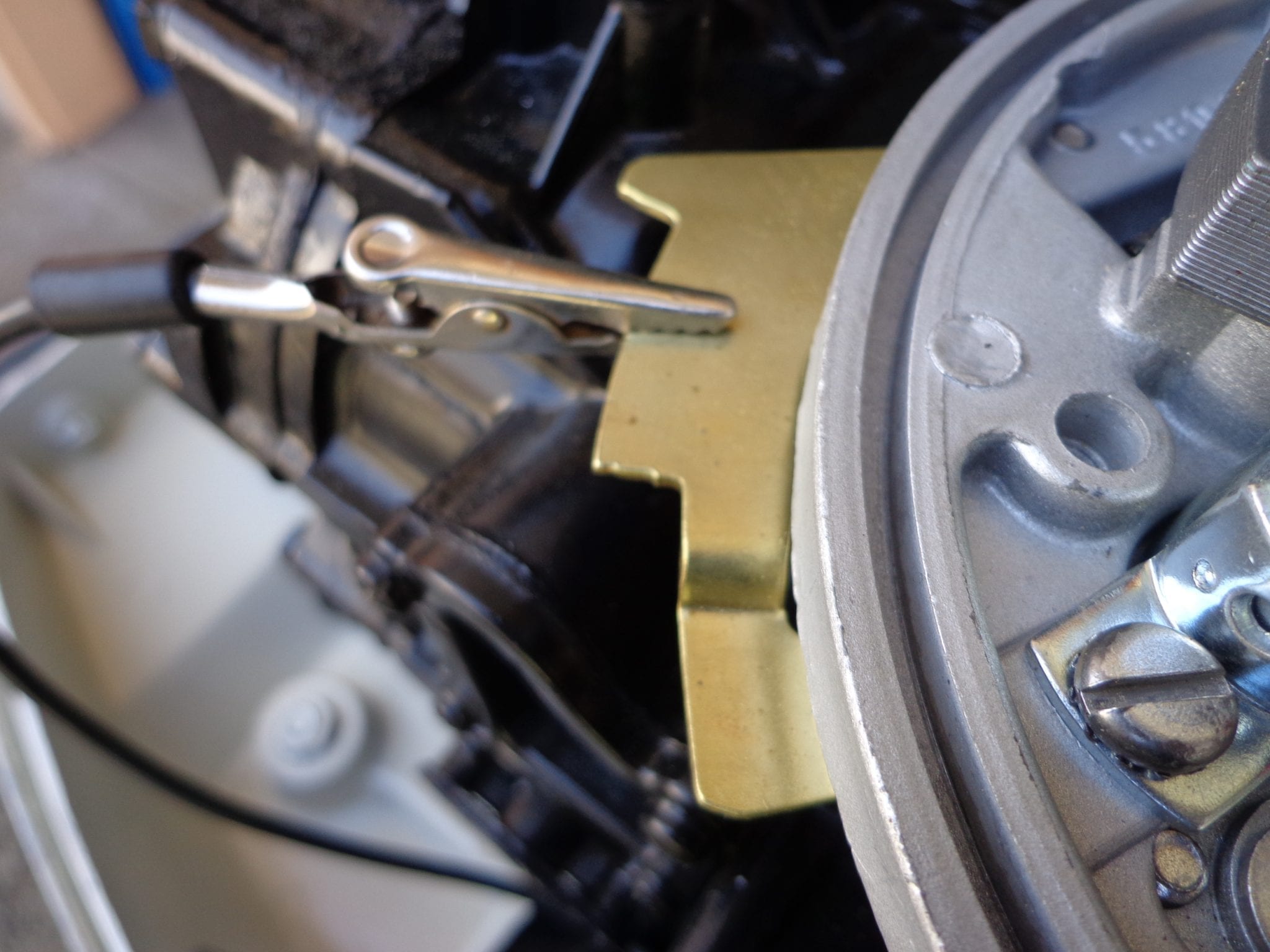
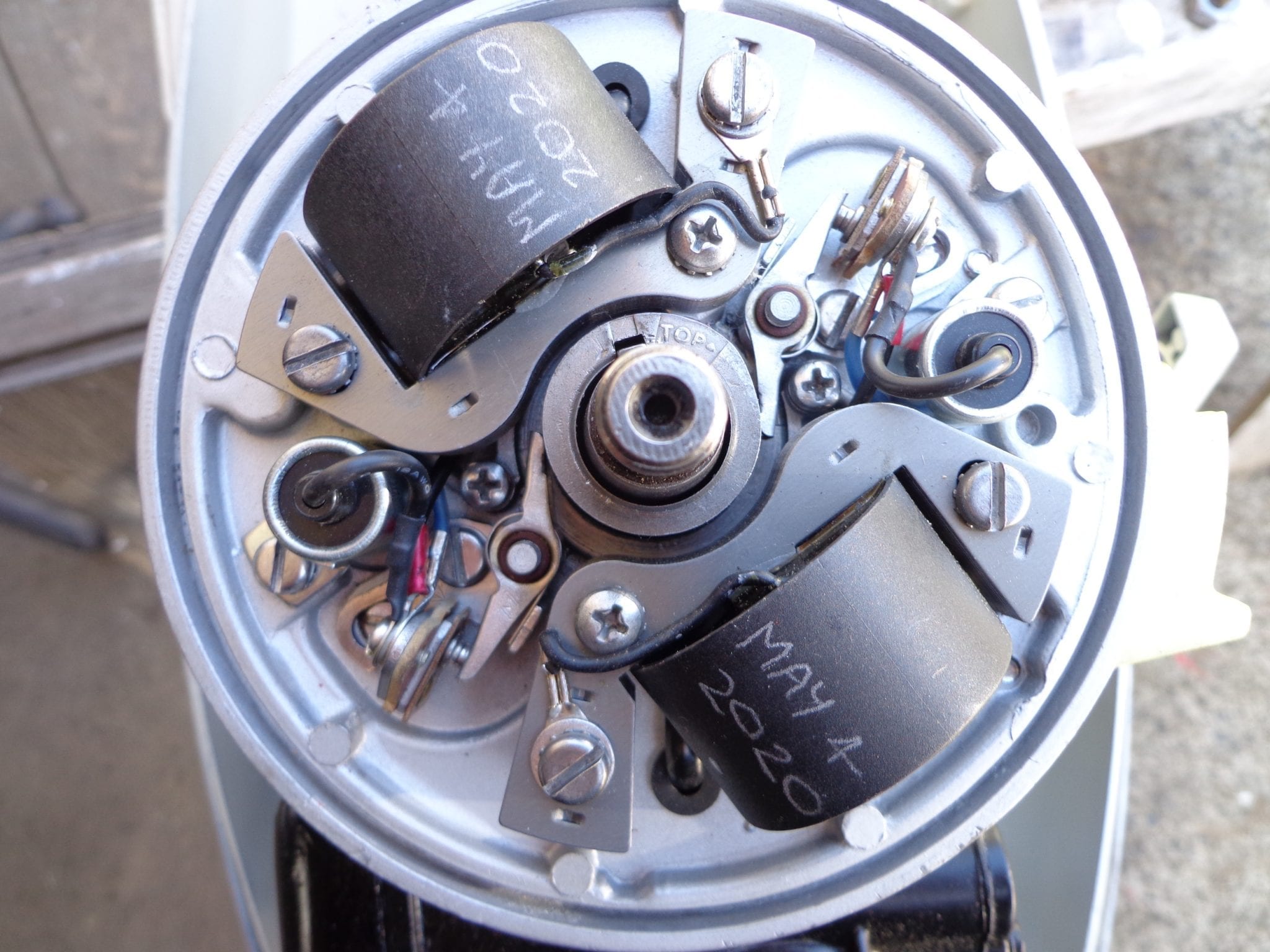
Here’s a QD 24 I did yesterday using a non tone multi meter and a set of leads with alligator clips on them. One lead goes to a good ground on the mag plate and the other lead clips onto the screw holding the wires on to the points. This lead could also be clipped onto the wires for the kill button once their connection is undone.
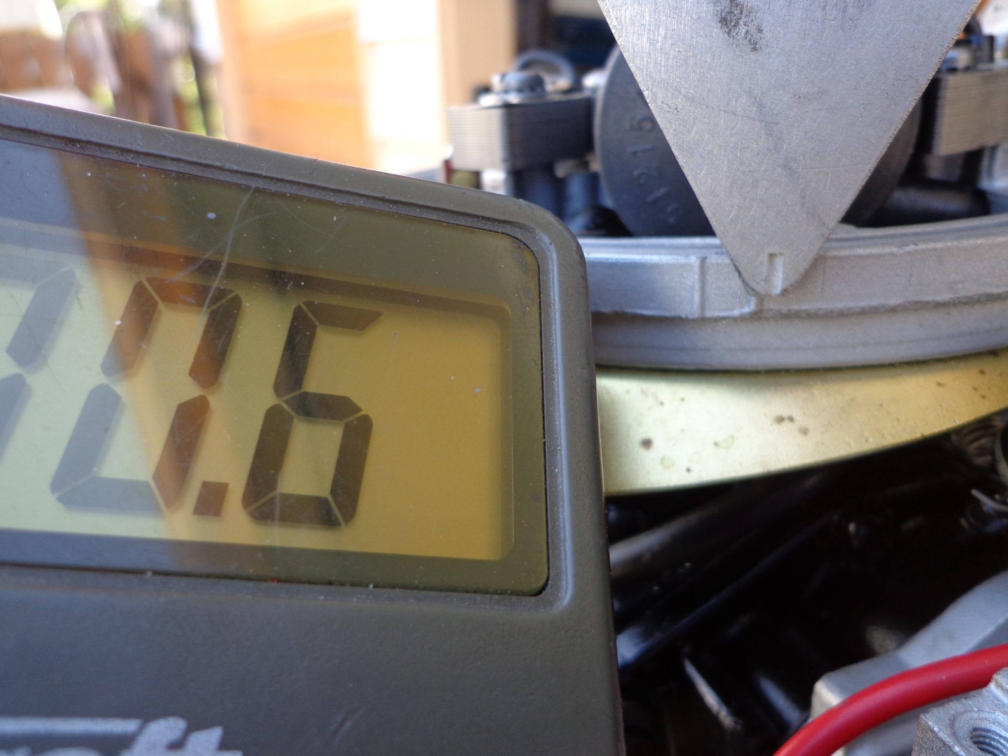
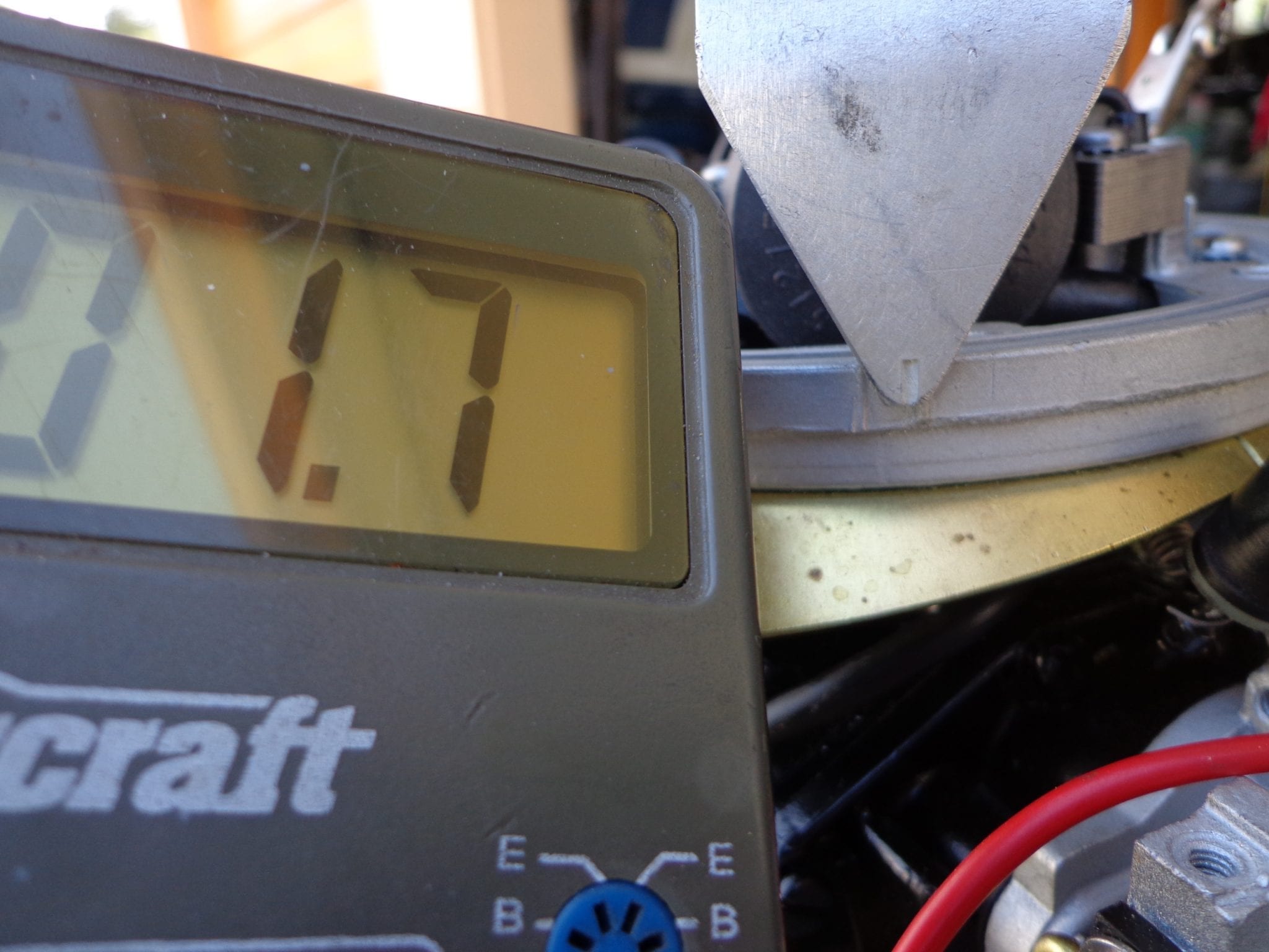
The leads I’m using themselves have about 0.5 ohm resistance in them so the numbers appearing on my screen are only for reference. With the points clean, polished, and closed, and the meter at its lowest setting, I get a reading of 0.6 ohm just as the pointer is approaching the timing marks. While slowly moving the timing tool and watching the meter at the same time, I get a reading of 1.7 ohms just as the points open and the meter reads the coils primary resistance instead of directly to ground thru the points. Turning the adjusting screw slightly will determine when the points are opening in relation to the timing marks. Maybe try it again and ignore the tone and read the meter instead?
 May 6, 2020 at 12:12 pm #202198
OK, this is an interesting approach. I have always set the point timing with all the leads disconnected from the points…But, just reconnecting those leads and tightening the screw can affect the gap/timing slightly… Doing this procedure with the leads connected, using the slightly higher reading when the points open, is easier and more accurate, provided you have a good ohm meter that can read low values accurately.
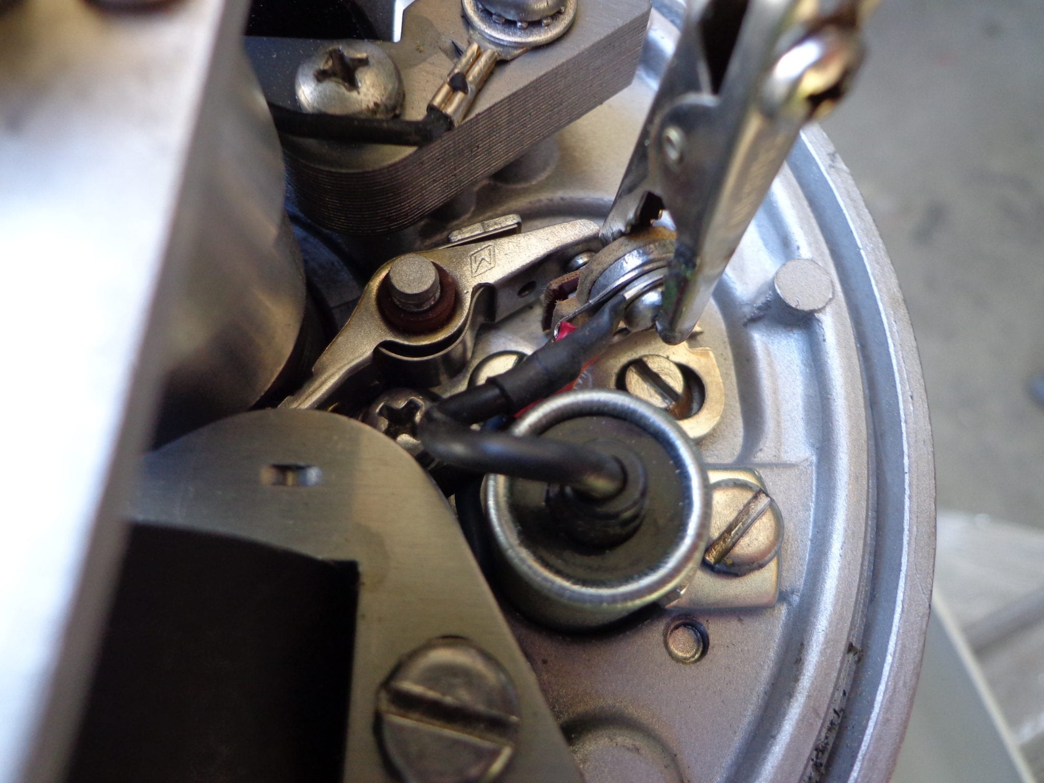
Is there a reason you don’t have the little wire clips on the points? Perhaps you just didn’t get to it yet….May 6, 2020 at 12:27 pm #202201Good eye! Both the retaining clips and the copper continuity clips weren’t installed yet when the photos were taken but they were before the flywheel was torqued on.
May 6, 2020 at 5:54 pm #202233I have never heard of removing the adjustment cam screw? Are we certain that the mag plate pivot bushing isn’t worn out? Of course if you are using Sierra points, they are very poorly made and won’t hold their adjustment…..too loose and sloppy.
May 10, 2020 at 11:34 pm #202739I tried the way Mumbles described and that by far is the best way to do it. I’ve been doing it before by disconnecting the wires at the points and using a flashlight connected to the points and ground like some of the manuals show. The downside on that method was you always had to reconnect the wires and that brought in error like Fleetwin mentioned and you couldn’t really go back and verify it without disconnecting it all again. Maybe I’m misinformed, but I think the disconnect (no pun intended) is that most of the manuals on this were made before digital multi-meters were around and so the better method with the multi-meter and leaving the wires connected isn’t described in the common service literature from that era.
-
This reply was modified 3 years, 11 months ago by
-
AuthorPosts
- You must be logged in to reply to this topic.