Home › Forum › Ask A Member › Remote Start 9.9/15hp OMC wiring diagram
- This topic has 11 replies, 5 voices, and was last updated 5 years, 5 months ago by
fleetwin.
-
AuthorPosts
-
February 14, 2020 at 3:12 pm #194846
I have one of these motors that I intend to set up with dual controls as a kicker motor. I have been looking through the service books but cannot find the wiring diagram for the older style remote start/kill switch wiring that has a choke solenoid, NOT the ‘newer’ primer solenoid. The motor I have is a 1984 model.
Does anyone have one or be willing to explain which wires are connected to where. I’d like to set it up with a common key switch that has the 6 terminals used on all the OMC outboards.
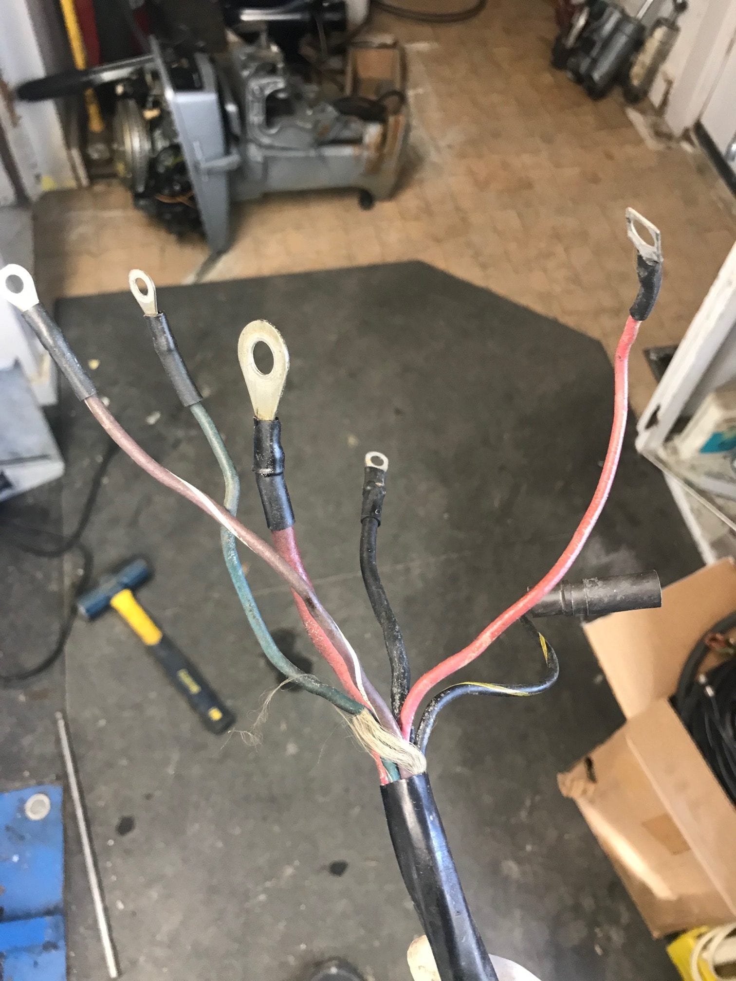
The wiring harness coming from the engine has the following, but some of which I am not quite sure what they go to (my initial thoughts below):
1. Thick red wire with larger eye-ring coming from neutral start switch on motor – ???
2. purple/white – power to the choke selenoid – key switch C
3. Single amphenol plug black/yellow wire – to kill switch – key switch M terminal?
4. Thinner black wire – grounded to block – to NEG battery terminal
5. Thinner red wire with small eye-ring – to battery + terminal from alternator
6. Green wire – ???What has me itching my head is where is the power to the engine supposed to come from as there are no battery cables attached to the motor; I see a black ground and red lead going to the starter from the neutral start switch (on the SB side of the powerhead), but no battery leads from the motor. I suppose this is because these small starters do not use a solenoid normally, so the power is going through the key switch out to the motor in the same manner (in line switch)?
The green wire is snipped at the motor side too, terminating near the alternator terminal block. Need to figure out what this is supposed to be connected to.
A wiring diagram would be quite helpful!
-
This topic was modified 5 years, 5 months ago by
johnyrude200.
-
This topic was modified 5 years, 5 months ago by
-
This topic was modified 5 years, 5 months ago by
-
This topic was modified 5 years, 5 months ago by
 Mumbles.
February 14, 2020 at 5:03 pm #194861OK, well that blue wire is a mystery….I am assuming there is a black plastic junction box that is mounted in the boat somewhere, correct?? If so, the solenoid is inside the black junction box, am I correct? The tiller start engines don’t use a solenoid, but I am thinking there is a solenoid inside that black junction box…You wouldn’t be able to run starter current up to, and back from the key switch….
If this is what you have, then the thick red wire goes to one side of the neutral start switch, like you said, and you have the other wires correct also…..
You mentioned the blue/green wire is snipped at the engine end, but what is it connected to on the engine? Any signs of the blue/green wire at the key switch? Post some pictures of inside the junction box and the key switch connections.. I supposed the blue wire could be used for a tach connection, but not sure….
You won’t find a wiring diagram for this set up in the service manual, because this remote set up was considered an accessory, OMC had separate manuals for accessories back then…February 14, 2020 at 5:46 pm #194866Unfortunately all I have is the motor. I looked through some parts bins and found another one of these harnesses I had put aside before. The green wire at the motor end had, what appears to be a factory sealant on to terminate the line on it so perhaps it isnt used for anything, possibly a tach lead as you mentioned.
The green wire on the motor I am talking about terminates near the tach/yellow/grey rectifier lead but I see no evidence of it being connected to anything on the motor.
Maybe I can find a kit on ebay with the original instructions. Otherwise Ill just have to wire up a simple push button start, stop, and choke set up. Would like to have a key switch but I guess buttons would still work.
February 14, 2020 at 6:30 pm #194873Not that it helps much, but here is the remote start kit so you can see what’s involved
http://www.marineengine.com/parts/johnson-evinrude-accessories/index.php?year=1984&model=Electrical+1984§ion=Remote+Starting+Kit+9.9%2C+15&yid=34144&mid=34145&sid=37095February 14, 2020 at 7:25 pm #194878Yeah frank, that’s the one all right. I guess a solenoid set up is necessary, so I should probably just copy what a larger motor would following for a wiring configuration.
February 15, 2020 at 7:57 am #194917How do you know the harness you have is the correct one that was supposed to be used? Perhaps someone just “made something up” from an old harness laying around. In any event, it will surely work OK. Find one of those old PTT harness with the large external box and use that box for the solenoid….Seal the blue wire off and don’t worry about it….
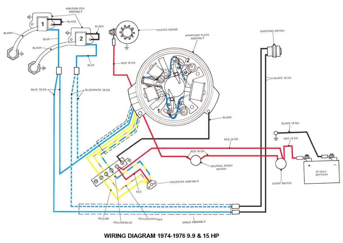
February 15, 2020 at 12:58 pm #194957Here’s the wiring diagram for earlier electric start 9.9/15 horse motors to help give you an idea what is what under the hood. It should apply to your ’84 model to except for the ignition system.
 February 17, 2020 at 9:39 am #195128
OK, another stray neuron just fired in my brain….That blueish looking wire is probably the negative battery cable! That other ground lead brings ground up to the key switch so the stop circuit will work…. Do you have a picture of the other end of this harness, how long is it? I’m thinking this harness shouldn’t be very long because it ends up in the little junction box, kind of like the older engines that used a junction box.
February 17, 2020 at 6:13 pm #195204The picture I posted is of the solenoid box side of the wiring harness. The other end is still wired to the motor. The green wire (there is no blue wire) is terminated at the motor and not connected to anything, and as I had mentioned earlier I found another one of these harnesses I had removed from another motor with this set up to find that the blue wire, on the motor end, appears to have a factory sealant on it to stop it from being used. Although, it’s possible that was done by someone else then the factory and this is all just a coincidence.
Nonetheless, I don’t think it will be hard to just make a simple key switch set up just like you find on any of the other motors using the big red plug, and I have plenty of those lying around here anyway. If we do ever find the schematics for one of these it would be nice to have it since I do run across these types of 9.9/15hp motor configurations every so often.
-
This reply was modified 5 years, 5 months ago by
February 17, 2020 at 7:12 pm #195210I don’t know if this makes it any clearer or not. The original setup ran a hot wire from the battery to the starter only interrupted by the neutral switch (it used as doorbell switch to START). I would think you’d need to insert a solenoid somewhere along the way if you want to run that function back to your key setup. The kill switch wouldn’t be a problem.
-
This topic was modified 5 years, 5 months ago by
-
AuthorPosts
- You must be logged in to reply to this topic.