Home › Forum › Ask A Member › Row Boat Motor Magnetos
- This topic has 74 replies, 15 voices, and was last updated 7 years, 2 months ago by
 Buccaneer.
-
AuthorPosts
-
October 19, 2018 at 12:37 pm #84630
Jim, that’s an interesting engine. Was that a "one off" or did it
go into mass production?Good advice on "over speeding" the Wisconsin. The mag does have
a kill button on it. I know my current mag isn’t ideal, having non-adjustable
spark advance, and spark in only one direction, etc., but I was
hoping to get the Wisconsin running while my uncle (who gave it to me)
is still walking this earth.I could retard the mag by pulling the flywheel up, and setting the drive
gears "back" one tooth. Not sure what that equals in degrees of timing,
but both drive gear on the flywheel, and driven gear on the mag drive shaft,
have 20 teeth. Doing some math, which isn’t my favorite thing, I come
up with 18 degree’s retarded by setting the gears back one tooth.
Not sure if it would start retarded that much. Possible I could mess with
the points in the mag to retard it a "tad".Plan "C" was to convert the Bendix mag to a distributor, using battery
and coil, but it still wouldn’t have any advance, so I’m in no hurry
for that plan. Not sure I can engineer a battery ignition with spark advance.
Thanks for the hep!quote JimParrott:Buccaneer,
Make sure you have a kill switch hooked up to the magneto in case it over speeds. Slow turning 2 strokes are controlled primarily with timing. I would suggest that you start out with the timing 10-20 degrees retarded and advance as needed. You fuel mixer dosn’t appear to have a throttle control so it won’t be much help in trying to slow it down. The stem being sloppy shouldn’t be much trouble as long the valve is seating. Sounds like your spring will be fine since it’s opening. As Tubs stated pulling thru compression is the way to start it. Bumping against compression is more of a buzz coil battery ignition setup starting procedure. If planning on running on a boat you will need to be able to adjust timing while running. I would suggest finding a magneto that is adjustable, or converting it to a battery buzz coil type ignition system.
Below is a link to a engine I have, that by design of the make and break ignition system cannot be retarded past TDC. In order to run it without a load, the throttle in barely opened to keep it from overspeeding. Restricting the air this much, causes it to cycle multiple times between firing.
Jim
https://m.youtube.com/watch?v=EI0k5zaj4X0Prepare to be boarded!
October 19, 2018 at 12:40 pm #84631You guys get an "A +" for ingenuity on that one!
quote JimParrott:My friend JB was given an engine at a show that was missing major parts. We decided to start it with minimal fabrication efforts. Having a buzz coil ignition system is a handy tool to have. We simply used some rigid house wire and a bolt to fabricate a make shift timer and a fuel wet rag for a carburetor. In a short time we were able to fire up this old marine engine.
Check out the short video below.Prepare to be boarded!
October 19, 2018 at 2:08 pm #84641Buccaneer,
I bought the engine off eBay as an unknown, and after 2 years we were able to identify as a Kowalsky Simplex Marine Engine. It is the only known survivor of this model Kowalsky. John Kowalsky was a great inventor, with The Verona PA Historical Society celebrating his name yearly.
A buzz coil is very simple to make and I can help you with that if you want to go that route. A timer would also be easy to make and I think you could easily adapt a set up that would provide a reliable, adjustable ignition system on a budget. If the correct mag is located you can convert back, but the battery ignition would start and run better. I’ll get some pics of simple timers and a buzz coil and post them for your viewing pleasure.
Jim
October 19, 2018 at 4:12 pm #84654Jim, I’m somewhat familiar with buzz coils and timers,
as I used to play with "hit and miss" engines. I still have
a GRAY stationary engine with said ignition. The hit
and miss engines I owned did not have any type of
timing advance, as they were governed to run one
speed. If you have any ideas on how to set up
a battery and buzz coil and have the timing
adjustable, that would be great.
Thanks!Prepare to be boarded!
October 19, 2018 at 5:43 pm #84658Buccaneer,
I assume your engine was likely offered with battery or magneto ignition, and obviously had the magneto option. Is your crankcase machined for a swing timer?
October 19, 2018 at 6:36 pm #84659Jim, I don’t believe my the Model M was offered without a magneto,
but there were certainly some models during some years that had the
Evinrude style timer below the flywheel.
Craib’s website shows some for 1913, and I have an ad for 1915 showing
a timer set-up.
One ad said all 1914 models equipped with a high tension reversible magneto.
That said, I’m not exactly sure what year mine is.
The upper crankcase does not looked machined for a timer, but
there may be room to rig one up.
One motor on Craib’s site appears to have been converted from magneto,
to some sort of timer affair running off the magneto drive shaft.
http://www.cailleoutboards.com/rowboat/ … -002f.htmlPrepare to be boarded!
October 19, 2018 at 8:12 pm #84661Buccaneer,
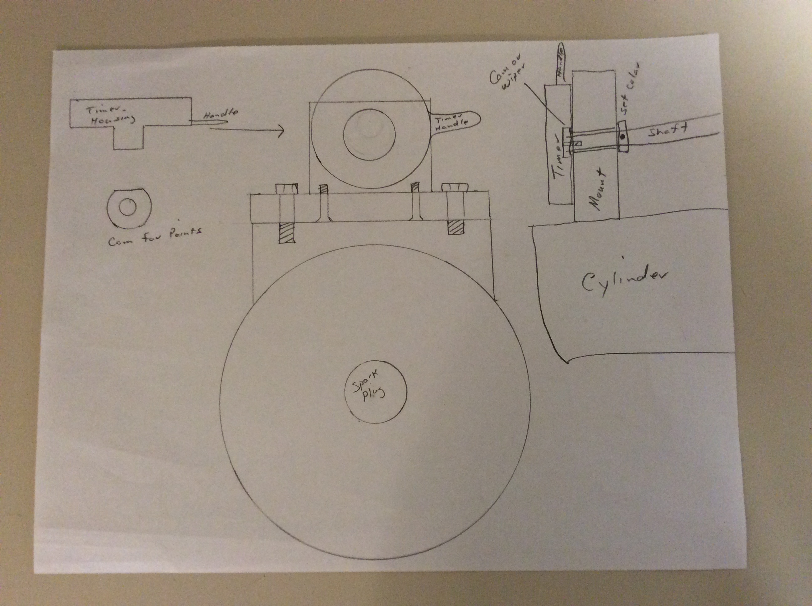
Do you have access to a lathe? I think a simple timer such as the ones used on inboard engines could be fabricated to take the place of the mag, or you could use a swing timer that would look more original. Please post a picture of the bottom of the flywheel. I will make a few drawings for suggestions. Having problems with posting pics right now and will be out of pocket til tomorrow..
Thanks
JimOctober 19, 2018 at 11:46 pm #84668Jim, Yes on the lathe. Don’t have any photos of the bottom of my flywheel,
but it should be the same as the one below. Just realized after looking
at that photo, that there probably wouldn’t be room to mount
a Evinrude type timer on the top of the crankcase, as the gas tank
mounts too close. Not sure what a "swing" timer is, but look forward
to your suggestions.
Thanks!quote JimParrott:Buccaneer,Do you have access to a lathe? I think a simple timer such as the ones used on inboard engines could be fabricated to take the place of the mag, or you could use a swing timer that would look more original. Please post a picture of the bottom of the flywheel. I will make a few drawings for suggestions. Having problems with posting pics right now and will be out of pocket til tomorrow..
Thanks
JimPrepare to be boarded!
October 20, 2018 at 2:37 pm #84686I was thinking about how other magneto’s that have adjustable timing
advance "worked", and remembered that I had an old tractor magneto
off a Farmall F-12 in storage the last 36 years, so I dug it out and
it’s pretty "high tech" for the 1930’s in how it works.
The Farmall mag has a drum that the points mount to, that
rotates inside a bore. The drum’s rotation is limited via a pin in the bore
and a slot in slot in the drum. The cover engages the drum to advance or
retard the timing.
I don’t see a way to adapt the same idea to my magneto. I still think there must
be a way to rig up a movable contact points plate with lever,
but it’s not coming to me.
The Farmall mag is cleverly designed so the coil wire that attaches to the
points does not move or twist around. That would just be one
consideration.
Any magneto engineers "out there"?Prepare to be boarded!
October 20, 2018 at 3:51 pm #84694Buccaneer,
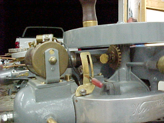
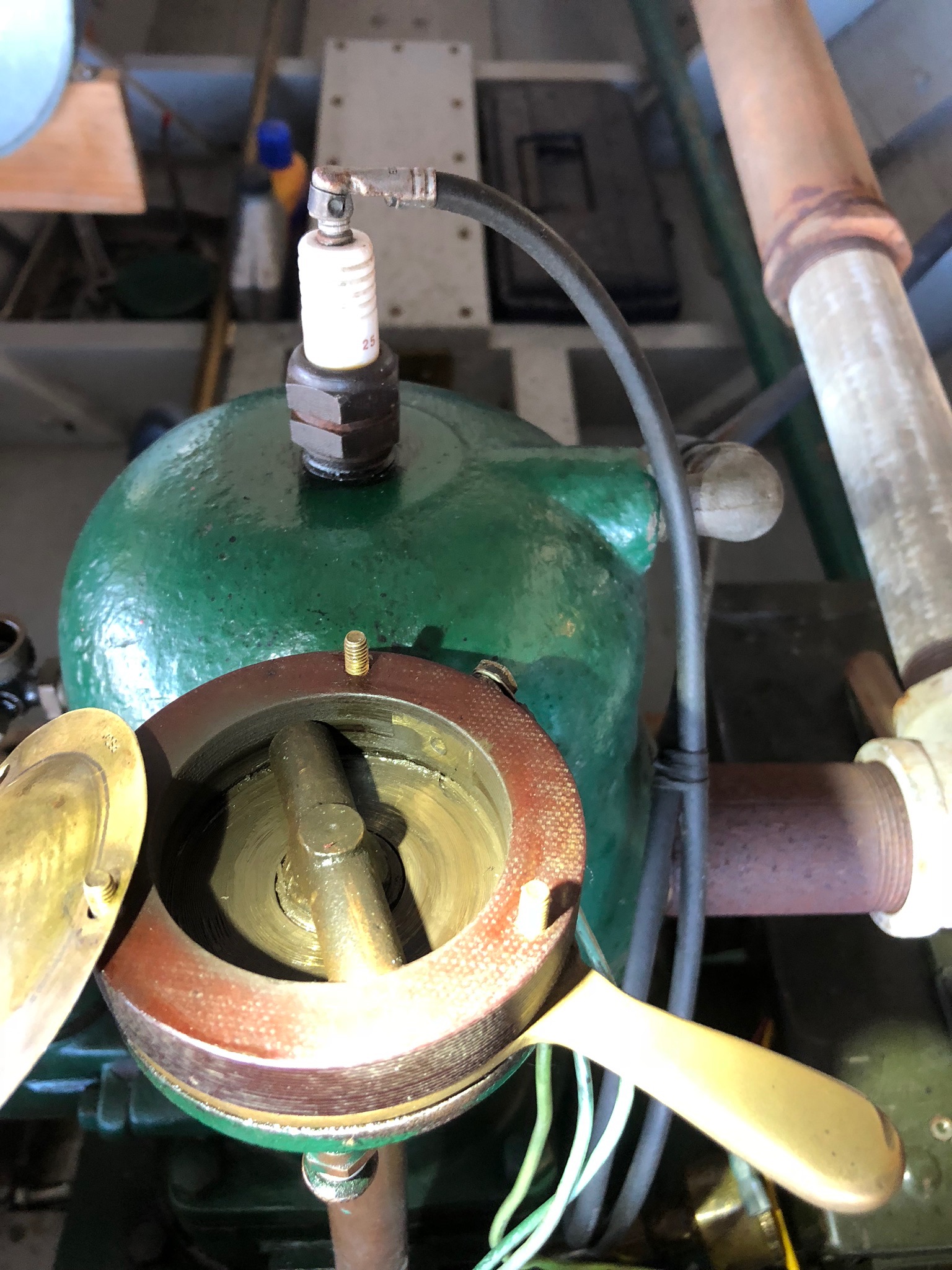
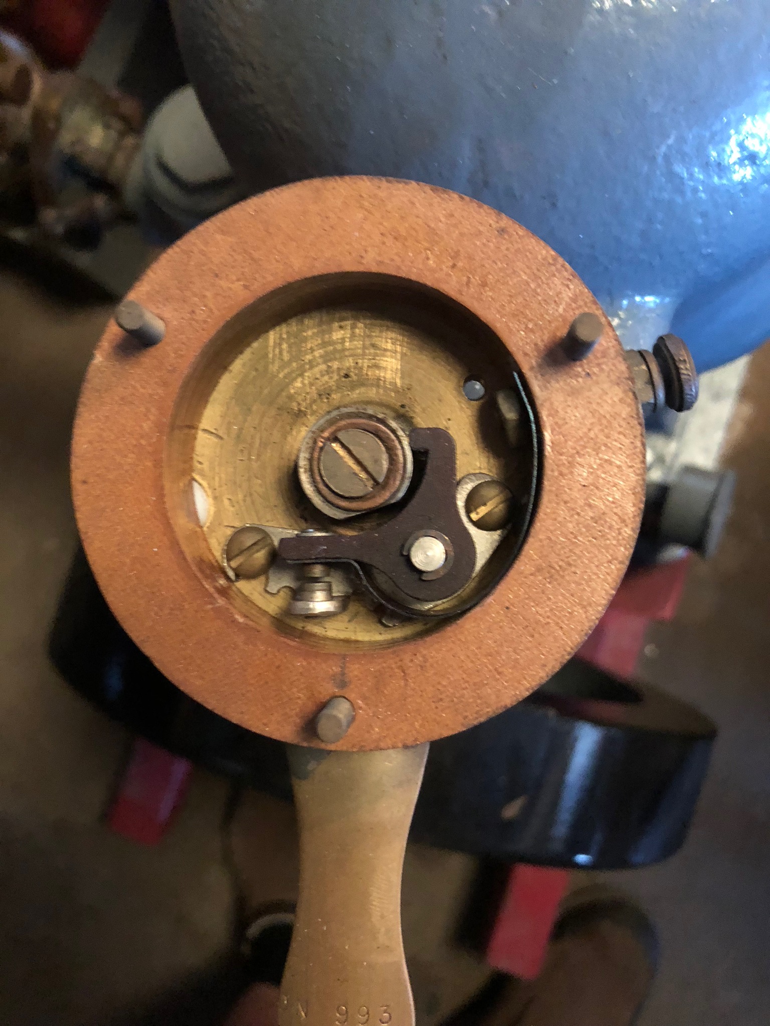
Attached are some pictures of some jump spark ignition timers. Using a buzz coil spark occurs when the circuit is closed via points or wiper. The first pick shows an early Lockwood that has a spring loaded plunger that contacts a brass contact placed in the insulated ring. The next two is a later Lockwood converted to modern points. Last is a Ferro that the cam lobe simply swipes against a piece of spring steel which is insulated from the timer housing. Castings for the Lockwood handle and plunger are available as well as the covers. I use micarta for the insulating ring and cam lobe for these timers. A simple one piece housing can quickly be turned on a lathe with a suitable sized round of aluminum and handle added. A mount could be fabricated from some .5 – .750 aluminum plate. A short drive shaft, with a set collar on the engine side of the mount. A wiper or point set up with a insulated contact, buzz coil, cover and mount and your good to go. I hope this makes since. My shop is across town and no internet there, if needed I can go take some timers apart for more pics if needed. Will post some buzz coil info in a little bit.
-
AuthorPosts
- You must be logged in to reply to this topic.


