Home › Forum › Ask A Member › Starter solenoids – the different types
- This topic has 10 replies, 5 voices, and was last updated 3 years, 8 months ago by
joecb.
-
AuthorPosts
-
February 18, 2022 at 12:26 am #254812
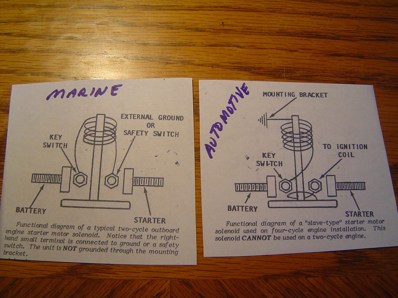
In a recent post about burning out the OMC mercury switches, the problem was correctly diagnoised as being the result of using an automotive style starter solenoid rather that the correct two cycle outboard type. I know that I had seen an explanation and schematic of the internal wiring somewhere… found it in a Seloc outboard service manual.
The Automotive style solenoid appears similar to the outboard type externally, but there are BIG differences electrically. In the automotive type the actuating coil is wired from one of the small terminals to the mounting bracket ground. The other small terminal is connected to the starter contact plate which closes to the large starter cable terminal. Upon activation that second small terminal sees the full 12 volts as does the starter.
In the two cycle outboard motor solenoid, the actuating coil is wired directly to the two small terminals, positive and negative. The body and bracket are electrically insolated.
To test as to which solenoid you might have… with the outboard type … 12 v to the two small terminals will activate the coil. With an automotive type you need 12 v to one small terminal and the mounting bracket to activate he coil.
Hope this helps… and prevents future “fried wires”
Joe B
February 18, 2022 at 4:35 pm #254876Does that statement hold true on a Chrysler 85 hp outboard?
“To test as to which solenoid you might have… with the outboard type … 12 v to the two small terminals will activate the coil. With an automotive type you need 12 v to one small terminal and the mounting bracket to activate he coil.”
February 18, 2022 at 5:10 pm #254877Joe, I don’t believe that is correct on the marine solenoids…they work just the same as the automotive. With a solenoid that has only one small terminal that terminal is powered by the key switch and the circuit is completed to ground internally. On the solenoids with two small terminals one terminal is grounded to the block/ground plate and the other is powered to activate it. I just went and grabbed one of my Evinrude service manuals to confirm.
February 18, 2022 at 5:30 pm #254878Dan, from what I understand and from what you say, my guess is that there may be different ways to close the coil 12 v circuit on outboard solenoids. Some may ground thru the bracket… the ones with one terminal. These I suspect would be mounted in a metal junction box as a common component ground. If an outboard application called for the solenoid to be otherwise mounted, then the two terminal type would be employed. In any case the significant difference between the outboard type and the automotive is that there is no internal connection to the full 12 v output from the large starter cable lug. The purpose for that connection in an automotive application is to connect a full 12 v to the ignition coil during cranking, bypassing the coil voltage drop resistor.
Joe B
February 18, 2022 at 9:22 pm #254906An outboard starter solenoid is completely different than a solenoid mounted to the automotive starter. The newer Mercruiser sterndrives have a slave solenoid that is used to power up the starter solenoid which yes has the extra term for the coil. All stand alone solenoids work the same way I believe…the small post/s activate the larger posts to give an instant 12 volts to spin the starter. At least that’s the way I’ve always understood the principles.
February 18, 2022 at 11:27 pm #254925There may be some confusion here… I’m not talking about the solenoid mounted on an automotive starter. It’s the automotive solenoid that looks like the outboard type and is typically mounted on the firewall under the hood. For younger folks, this would be considered “old style”.
“All stand alone solenoids work the same way I believe…the small post/s activate the larger posts to give an instant 12 volts to spin the starter. At least that’s the way I’ve always understood the principles.”
this is not true, and is the source of the problem with the fried wires that were discussed in the former “mercury switch” thread.
Tomorrow I will post some photos and a schematic that should clear up the issue.
Joe B
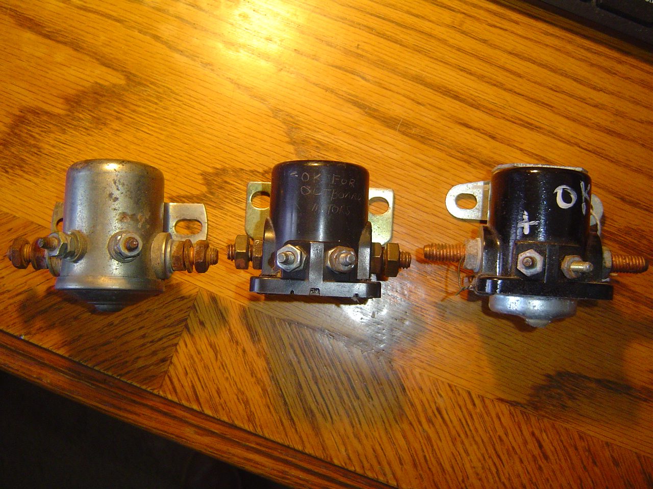
February 19, 2022 at 7:49 pm #254973Here is a photo of three starter solenoids. They all pretty much look alike, but there is a big difference in the one on the right. The two on the left are outboard marine starter solenoids. The one on the right is for automotive application. If you try and use that one for your outboard, it will cause damage to your wiring system. The difference is in the internal wiring, and grounding. In the marine units the body and bracket is electrically isolated. On the automotive unit the ground is thru the bracket.
Attached is the photo and copies of the schematic showing the internal wiring (Seloc manual)
Hope that this clears up any confusion… and saves a motor.
Joe B
February 19, 2022 at 8:35 pm #254999If things aren’t confusing enough, Ford (automotive) solenoids are usually marked “S” for start terminal and “I” for the ignition bypass terminal. So far, so good. However some outboard solenoids are also incorrectly marked “S” and “I”.
February 19, 2022 at 8:57 pm #255001Site with wiring diagram for Ford solenoid?
https://vintageautogarage.com/starter-solenoid-ford-mercury-lincoln-12-volts/
http://www.omc-boats.org
http://www.aerocraft-boats.orgFebruary 19, 2022 at 10:15 pm #255002Wow Joe, now that I see your diagrams I see exactly what your talking about. This is an eye opener for sure. I can’t remember ever seeing this type of starter solenoid….OMC and Mercruiser used Ford engines for a short time but I don’t remember ever changing one of these. When I get a chance I’ll investigate some of my old service manuals. Sorry for doubting you…it was pure ignorance on my part.
-
AuthorPosts
- You must be logged in to reply to this topic.


