Home › Forum › Ask A Member › Stevens tester
- This topic has 22 replies, 12 voices, and was last updated 3 years, 1 month ago by
Dave Willacy.
-
AuthorPosts
-
March 6, 2018 at 2:46 am #72040
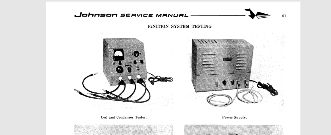
it is in the BIBLE book…………… page 61 and up for testing info and switch settings
boat info site BIBLE manual can be found
Attachments:
Joining AOMCI has priviledges 🙂
March 6, 2018 at 3:34 pm #72061The boatinfo site has been down; perhaps permanently. Garry does have the Bible Johnson manual in his dropbox however…..
March 6, 2018 at 6:19 pm #72065the boat info site works fine just click my link and accept adobe flash version 9 suggested
I have no problems accessing it ….and I snipped that picture out of it
sorry I had pasted my own C drive copy …………..the http address will get you there
Joining AOMCI has priviledges 🙂
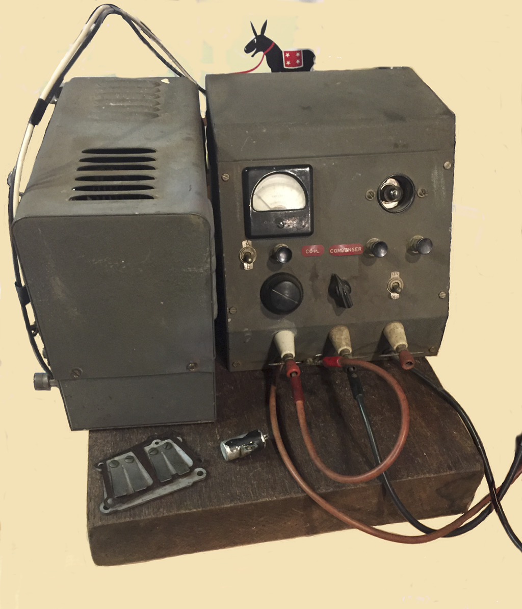
March 7, 2018 at 5:11 am #72099While we were living in the old neighborhood, my Stevens equipment was donated to the neighborhood improvement association while the wife and I were at our doctors office. The house was broken into 39 times that year . . .

 March 7, 2018 at 12:36 pm #72106quote Garry in Tampa:While we were living in the old neighborhood… The house was broken into 39 times that year . .
I understand why you call it the “old” neighbourhood. I didn’t know places like that actually existed.
Wayne
Upper Canada Chapteruccaomci.com
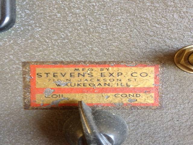
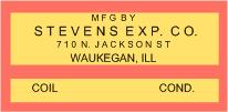
March 7, 2018 at 1:28 pm #72107If anyone’s interested, here’s the decal in the center of the old Stevens Tester, and a repro file that can be used to print one out. I have not made these in decal format.
I also have a schematic for the unit, and have successfully brought three of the vibrator tubes for these units back to useful life.
PM me if you want the file for the decal repro or tips on getting the vibrator to work.
Tom Manley
Attachments:
 February 25, 2022 at 5:29 pm #255255
Well this is an old post but I happen to have a Stevens tester with power supply on the bench for repair. I am looking for a definitive answer to What is the correct voltage output for the auxiliary power supply? Does some one have one that can measure it? Any specs that state DC output? Anecdotally the manual says to hook up the test box to 6 v. Anecdotally I have heard folks measured 8V. Given that the current specs in the manual for each coil assumes a fixed voltage of a certain value it makes sense to get it right. The old selenium rectifier in them used to drop a ton of voltage. A modern silicon bridge works great but yields too high a voltage. 20 plus.
February 25, 2022 at 6:54 pm #255260Here’s a little info on replacing a selenium rectifier with diodes.
http://www.w3hwj.com/index_files/RBSelenium2.pdf
I ran into the same problem with mine.
T
February 25, 2022 at 8:18 pm #255265Um, thinking back, isn’t the voltage applied to the coil controlled by the operator turning up a rheostat until the coil starts producing sparks? As the voltage goes up, so do the Amps which are indicated on a meter and compared to the specs. At least that’s the way I remember it.
February 25, 2022 at 8:48 pm #255266It works as you remember, Frank. However, it is the power supply for the Stevens tester that Dave is repairing. The power supply output should be constant. Once Dave knows the expected output voltage he can determine how to best drop the 20V down to the desired voltage. I thought the power supply was supposed to be a constant 8V output. Manual says to use a 6V power suppply (car battery so actually more like 6.4V) or a hotshot battery (7.2V). I can’t find any specs other than frequency and amps.
Wayne
Upper Canada Chapteruccaomci.com
-
AuthorPosts
- You must be logged in to reply to this topic.