Home › Forum › Ask A Member › Scott McCulloch 25
- This topic has 22 replies, 10 voices, and was last updated 1 month, 3 weeks ago by
 Mumbles.
-
AuthorPosts
-
February 25, 2020 at 1:25 pm #195849
Hi Guys,
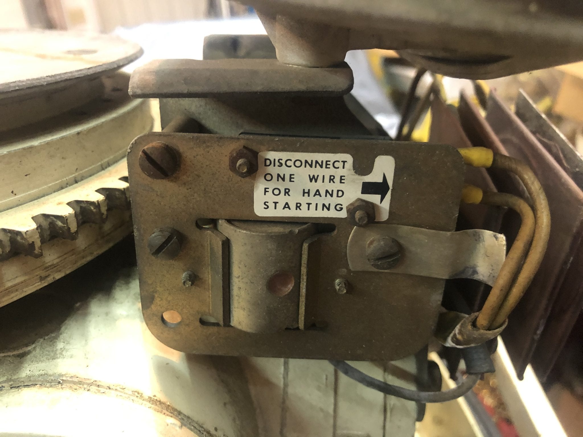
We just picked up a sweet little Scott McCulloch 25 yesterday and have a couple questions about this engine. This is an electric start model that has the battery ignition system, serial number 335 2581. Upon looking the engine over there is a device bolted the rear port side of the power head that has a message on it saying “disconnect one wire for hand starting”We believe it holds the ballast resister on the back side of the mounting bracket but couldn’t take if off to see. There also appears to be a cylinder near the bottom of the mounting bracket that looks like it might be a solenoid, but again we didn’t take it off to see what it connected to or how it was wired ?
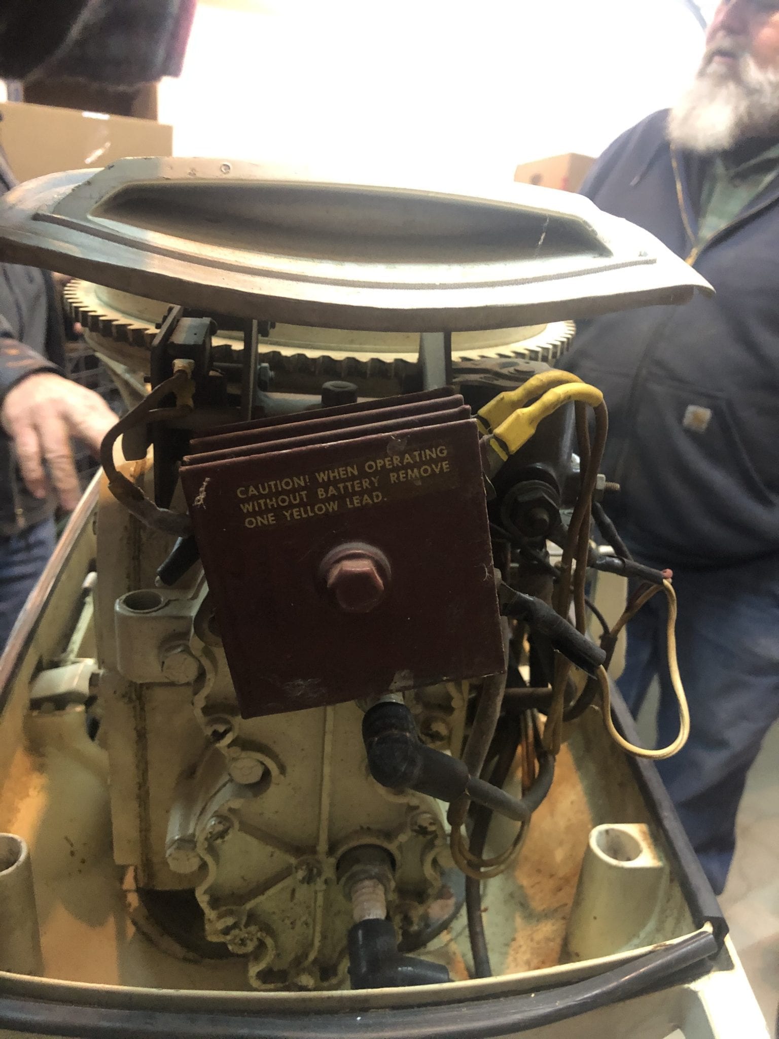
On the rear of the engine printed on the rectifier is another message saying “when operating without battery remove one yellow lead ” First of all we would like to know what year this engine is ! Secondly do these messages mean a wire has to be removed from both these devices to start if the battery is dead or disconnected, or do we just pull one wire from either the rectifier or ballast mount ?
I have three manuals for the years 1958, 1960 and 1962 that I have looked thru trying to find a part description for the device mounted on the rear port side of the power head, but could not find it in any of the manuals ? Hope somebody can shed some light on what the reason is for disconnecting these wires or why it is necessary when trying to start this engine with a dead battery ?
Thanks for any help provided
Geary
-
This topic was modified 6 years, 4 months ago by Mumbles.
February 25, 2020 at 3:07 pm #195859Well yours is a bit different than the one I had. Does yours have a magneto under the flywheel AND battery ignition?
DIsconnecting the rectifier makes sense if there is no battery, you don’t want to be generating current with no place to put it. I would suggest NOT using the charging system until you know it’s all up to snuff. Frying a rectifier is not good for your lungs.
I encourage you to follow through with this motor. I had one that I used to get my kids up on skis, it was a very dependable motor. Last I knew, the owner in Maine still uses it.
Tom
February 25, 2020 at 4:01 pm #195861I see model 335 as being a 1958 22hp, and a 335A as being a 1959 25hp.
The yellow alternator wires must be disconnected from the rectifier when running without a battery to prevent damaging the rectifier. As for the other gizmo, I don’t know what it is. I have wiring diagrams for 28hp, but it doesn’t show anything like that.
February 25, 2020 at 4:22 pm #195862I also have a 1960 service manual showing a 25hp wiring diagram that doesn’t show the mystery part.
February 25, 2020 at 5:46 pm #195868Guys, Thanks for the replies !
Tom, You can’t have it both ways, it’s either a magneto or it’s a battery ignition. The electric start 22hp Scott had a magneto with alternator coils under the flywheel to charge the battery, but this Scott 25 engine it just a battery ignition with the coils outside the flywheel ! There are two alternator charging coils under the flywheel that connect to the rectifier with the two yellow wires then a red wire from the rectifier that goes to the hot side of the starter solenoid to charge the battery !
What confuses me is why it says to disconnect one wire from one side of the device on the back of the engine and disconnect one of the alternator wires from the rectifier to start the engine with the battery dead or disconnected ?
Frank, I agree none of my wiring diagrams show this device ! My friend Paul just bought this engine after I persuaded him it would be a great outboard for his 14ft LoneStar ! He has the engine at his house so I can’t pull the mystery part off to see what’s behind it and how it works ? When we get it over to my house and we find out what it does I’ll post another entry about it’s workings ! I have the wiring diagram for the “62” 27.7hp but it is very similar the the 25 and doesn’t show that mystery device either ?
On a battery ignition system, If there is no battery or if the battery is dead, according to what I read on the device and on the rectifier you should be able to start this engine with a rope ! That tells me something is supplying power to the coils to fire it ! And the only thing in the system that can do that is the alternator, and why would it be necessary to pull one of those wires from the rectifier unless the alternator put out too much power and could cause damage to something else in the system ?
The Mystery continues, stay tuned !
February 25, 2020 at 8:02 pm #195875Well If that is true, I find it interesting that you can rope start it with a dead battery or no battery.. Possibly with a battery that is too low to run the starter. But it is almost universal that running with no battery may blow a rectifier. That’s because running on open circuit causes the alternator voltage to rise above what the rectifier can withstand.
Anxious to see how this turns out.
February 26, 2020 at 7:20 am #195891Begin forwarded message:
From: Gary Orloff <gerayorloff@icloud.com>
Date: February 26, 2020 at 6:40:49 AM EST
To: “Antique Outboard Motor Club,Inc” <noreply@aomci.org>
Subject: Re: [Antique Outboard Motor Club,Inc] Scott McCulloch 25
Hi Frank,
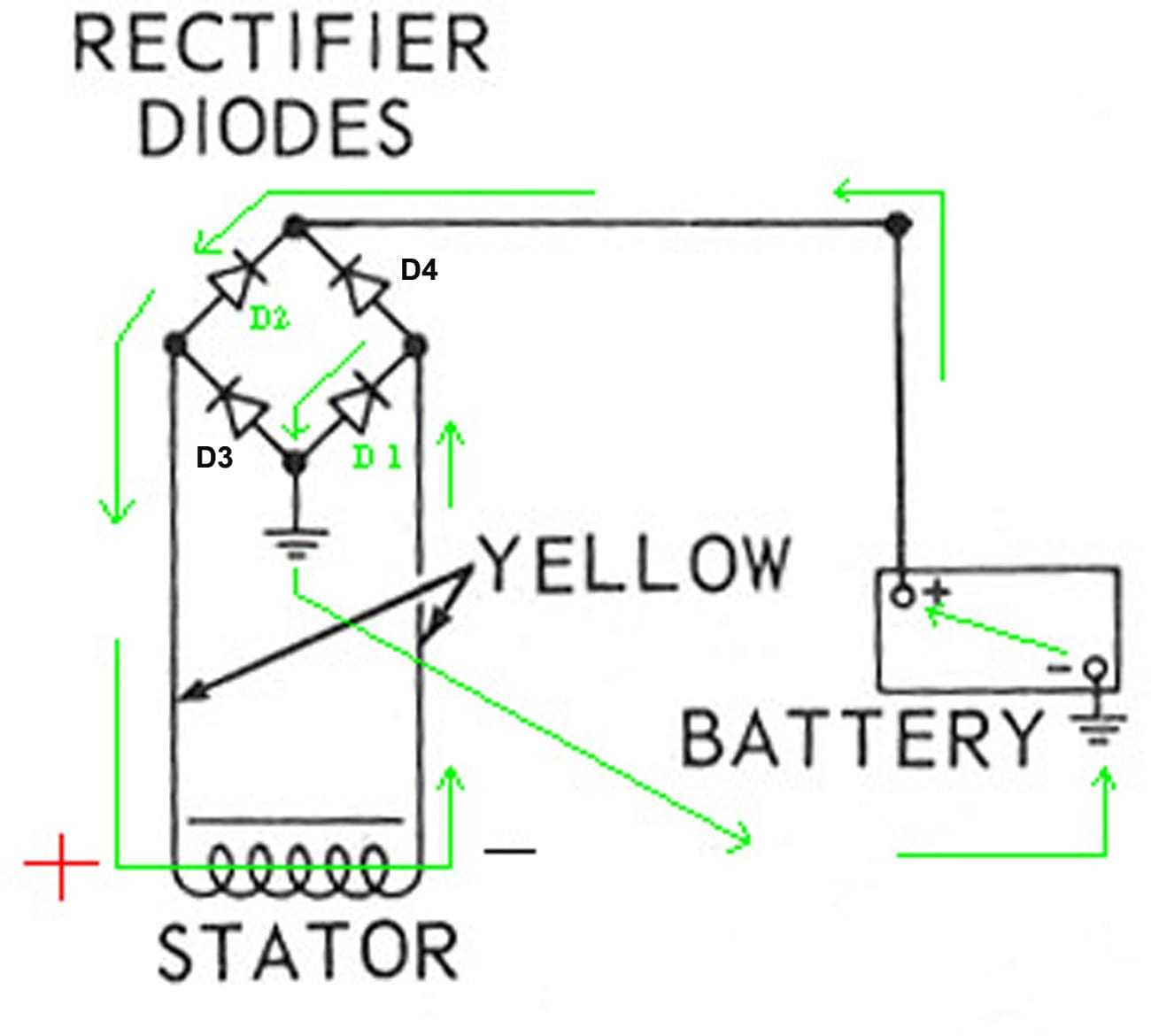
I’m starting to get out of my comfort zone when trying to figure out how this system works electrical wise ! I understand charging systems and how they work with the coils and a rectifier, but if a charging system has no load why would if burn anything out ? A rectifier is just a set of (usually) 4 diodes arranged to allow the positive and negative pulses (AC) from the coils to only go in one direction i.e. DC current. So doesn’t an alternator or even a generator only produce enough power to carry the load connected to it, the more load you put on it the more energy it takes to turn it ?
Without a battery in the system the alternator has to be what is powering the ignition system, and if we disconnect one yellow wire from both the ballast resister and the rectifier wouldn’t that cut the power produced in half ???On Feb 25, 2020, at 8:02 PM, Antique Outboard Motor Club,Inc <noreply@aomci.org> wrote:
frankr wrote:Well If that is true, I find it interesting that you can rope start it with a dead battery or no battery.. Possibly with a battery that is too low to run the starter. But it is almost universal that running with no battery may blow a rectifier. That’s because running on open circuit causes the alternator voltage to rise above what the rectifier can withstand.
Anxious to see how this turns out.
Post Link: https://aomci.org/forums/topic/scott-mcculloch-25/#post-195875
———–
You are receiving this email because you subscribed to a forum topic.
Login and visit the topic to unsubscribe from these emails.
February 26, 2020 at 10:47 am #195896This is getting almost off topic, but since there is such a “why” or “how” question, I am going to attempt to explain how an outboard alternator charging system works. So hang onto your hats folks, here goes.
First, I must say that this is how I was taught. See, my schooling was when I took a course in radio/TV repair, back when radios and TVs had vacuum tubes. The first lessons were on what electricity is and how it flows. One of the hardest things for me to grasp is that it flows from negative to positive. That is, it comes out of a battery’s negative terminal, flows through a load, and back into the positive terminal to complete a circuit. That is known as the “Electron Theory” and is how it REALLY flows. It would be almost impossible to understand how a vacuum tube works without the Electron Theory. Contrast that with the “Conventional Theory” which teaches that it flows from positive to negative–that is out of the + terminal and back to the – terminal. Since vacuum tubes are rarely seen any more, the Electron theory has more or less fallen into disuse and Conventional Theory used instead, because that is how most people THINK it flows. My comments from here on use the real Electron theory. If you insist on using the Conventional Theory, simply reverse the arrows.
Ok now that I have everyone confused, a battery supplies a voltage that pushes electrons out of the negative terminal, through a load, and back into the positive terminal. Now, for lesson two: To recharge that battery, a voltage that is higher than the battery’s voltage it applied to it, which causes the electrons to flow backwards through the battery, recharging it. That is, the charging current flows into the battery’s negative terminal and out the positive terminal and back to the charger source. EDIT: Corrected.
Finally, on to the charger and rectifier. But first, I must explain that the current flows through a diode in a direction OPPOSITE the direction of the diode symbol’s arrow and is blocked in the opposite direction (Electron theory). There is a reason for that seemingly backwards arrow, which I’m not going to get into. Reverse it if you want to think Conventional.
Following is a diagram of a simple outboard alternator, using a bridge rectifier (the most common type). Try to follow along, and bear with me.
The Stator Coil: Follow the green arrows. As a magnet passes the coil, a voltage is generated in the coil, one end will be positive, the other end negative, according to which end of the magnet passes by first. As the other end of the magnet passes by, the polarity of the voltage is reversed. For this study, consider the right end of the coil is negative, the left is positive. If the voltage exceeds the voltage of the battery, electrons will flow out of the negative end of the coil, through Diode D1, to ground, then from ground into the negative terminal of the battery (remember, this is backwards and charging the battery). After passing through the battery and out of the positive terminal they go back to the rectifier Diode D2 and to the coil positive end to complete the circuit. During this time, Diodes D3 and D4 are blocking current flow in the wrong direction. As the magnet continues, the coil ends change polarity and current now passes through D3 an D4, with D1 and D2 blocking, but never mind that for right now.
Disconnect the battery and see what happens: In the previous example, voltage is limited by what ever it takes to overcome the resistance of the battery. With no battery, voltage is only limited by the strength and speed of the magnet, and the windings of the coil. It can easily reach 100 Volts or more, for example. Now we have 100V pushing electrons through D1, but they do not go to ground because the ground circuit is open (no battery). Instead, they look at Diode D3 as a path back to the coil. D3 tries to block them, but lets say D3 cannot withstand more than 50 Volts in backwards flow. So here we have 100V trying to flow backwards through D3 which can only withstand 50V. Result is D3 burns up and the smoke gets out.
If you were able to wade through all this, good.
 February 26, 2020 at 1:21 pm #195909
Good Afternoon Guys!
I have a 1959 Scott McCulloch 25 hp Model 335 2809, Electric Start with Generator.
Hopefully I can help with this topic!
The “Disconnect one wire for hand starting”. When you turn the starter key to “ON”, voltage is sent from the battery to that solenoid (on the port aft area) to activate and “remove” the ground connection of the coils allowing the coils to fire.
Conversely, turning the starter key to the “OFF” position removes the voltage from the solenoid causing to solenoid to “close” and grounds the ignition system and shuts the motor down.
So if you are “hand starting” you need to remove that ground connection to allow the coils to fire.
By disconnecting one of those wires you have removed the ground connection and the coils will no longer be grounded and now be able able to fire.When you initially turn the start key “ON”, not crank, you should hear that solenoid activate, breaking the ground connection and ready to fire when you go to the crank and start position.
Hope I said that all in an understandable manner and correctly !!
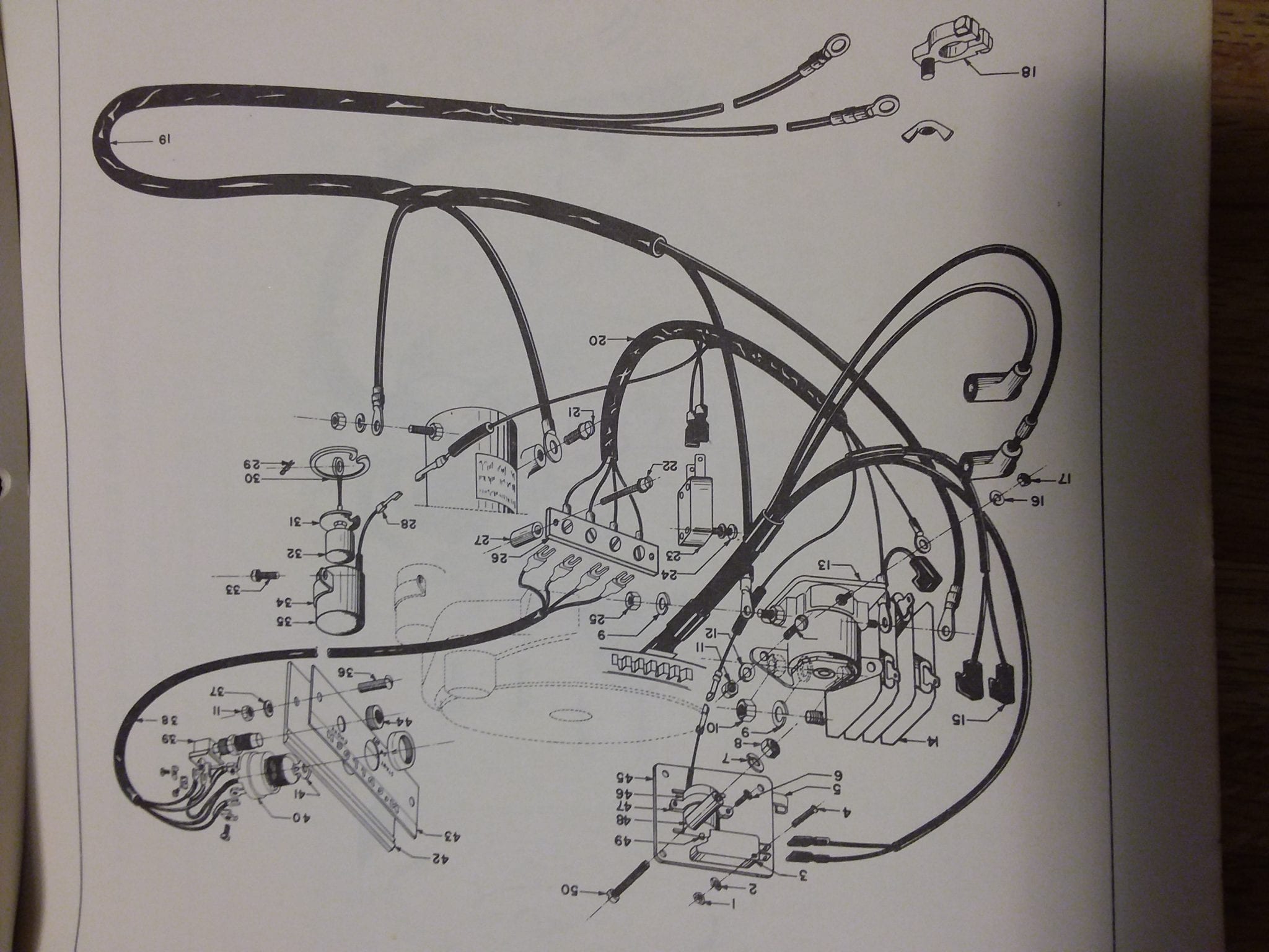
I am going to try to attach an Electrical Harness diagram. (We’ll see how that goes!)
Respectfully,
Bob
February 26, 2020 at 1:27 pm #195910Scott McCulloch Electrical Harness Attempt 2
-
This topic was modified 6 years, 4 months ago by
-
AuthorPosts
- You must be logged in to reply to this topic.